
Anal fixation device

a technology for fixing devices and anal tubes, applied in the field of anal fixation devices, can solve problems such as measurement errors, and achieve the effect of more diagnostically representative/reliable test results

Active Publication Date: 2015-09-17
MAYO FOUND FOR MEDICAL EDUCATION & RES +1
View PDF12 Cites 0 Cited by
  • Summary
  • Abstract
  • Description
  • Claims
  • Application Information

AI Technical Summary

Benefits of technology

The present invention provides an apparatus that allows for a more natural patient position when performing anorectal manometry, high-resolution manometry, or mano-defecography procedures. This leads to more accurate and reliable test results. The device assemblies can be used in conjunction with a toilet or toilet-like device, so the patient can be in a natural sitting position without the need for anxiety over making a mess during attempted defecation maneuvers. Additionally, the use of the device assemblies can reduce operator workload, and potentially eliminate the need for a second technician during the procedures. Furthermore, the device assemblies can reduce or eliminate measurement artifacts due to movement of the probe during the procedure. This is achieved by employing high-resolution manometry that ensures at least one sensor remains within the high-pressure zone of the sphincter.

Problems solved by technology

This kind of movement can cause errors in measurement.

Method used


Image

  • Anal fixation device
  • Anal fixation device
  • Anal fixation device

Examples


first embodiment

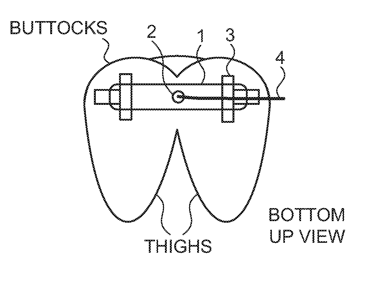
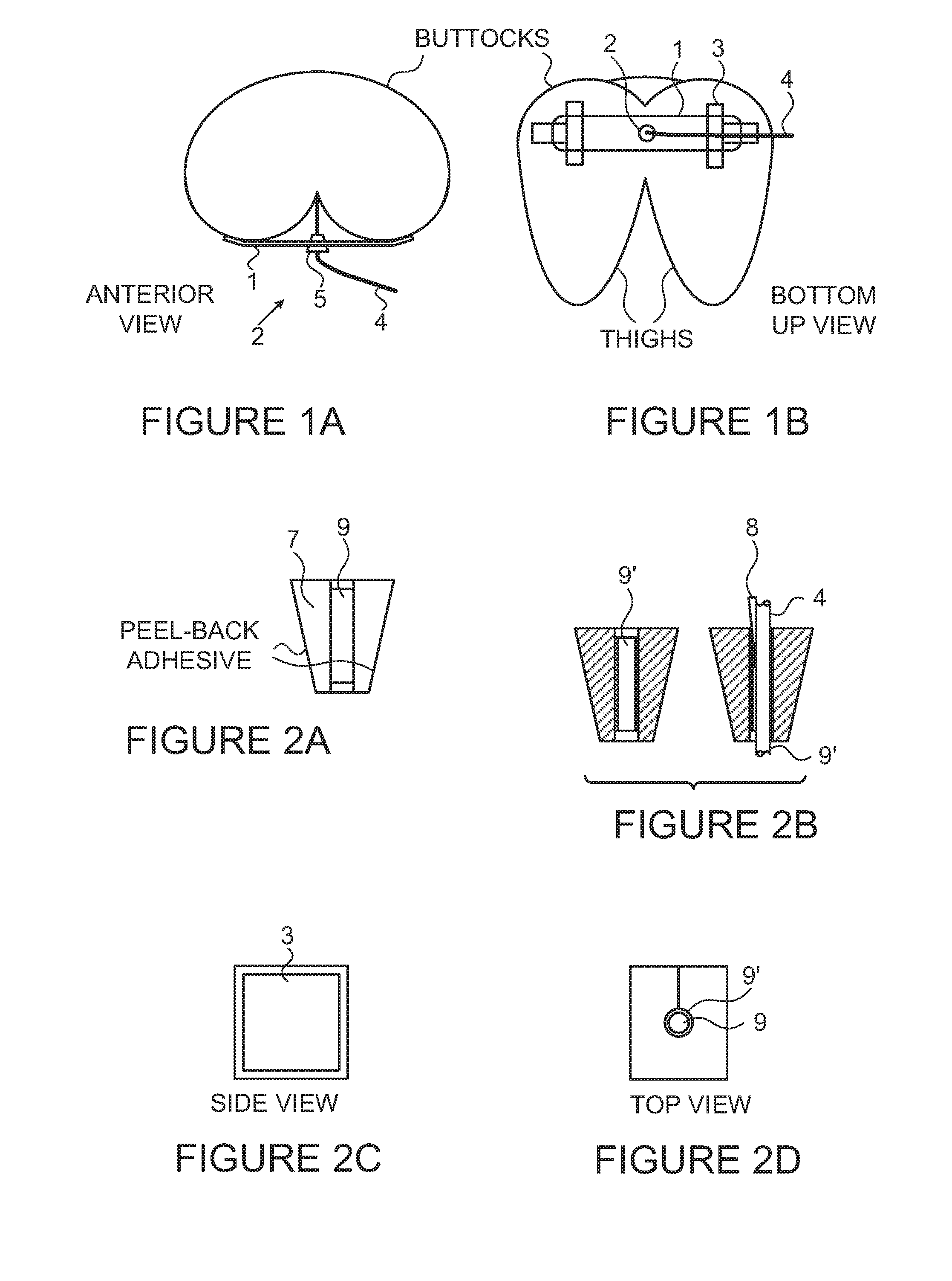
[0035]Advantages of this first embodiment include its manufacture simplicity and ability to provide a strong structure that securely holds catheter probe 4 in place, proximate to the buttocks.

second embodiment

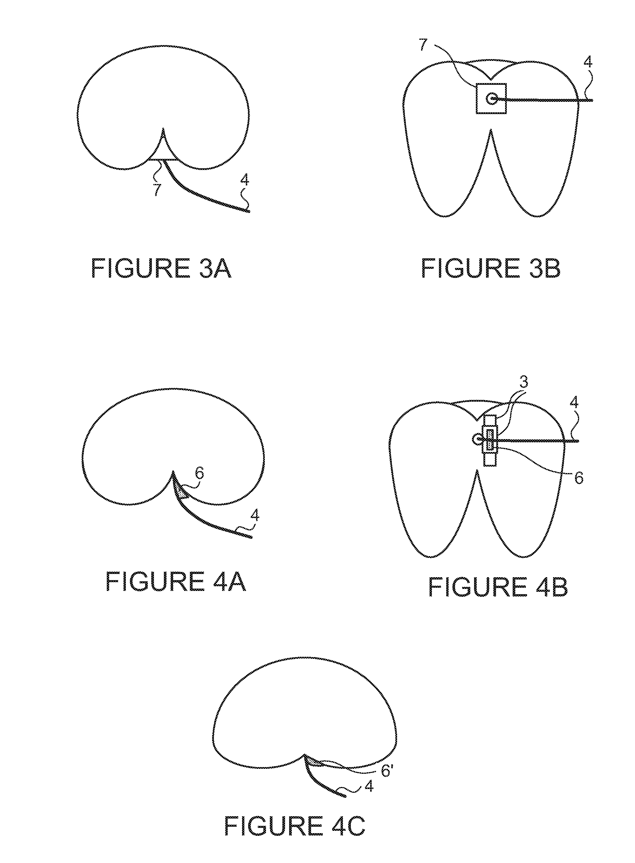
[0036]the present invention is shown in FIGS. 2A-2D. In this embodiment, a device that is in the shape of a full wedge 7 is fastened at (e.g., to both sides of) the interglutial cleft via a suitable adhesive 3.

[0037]A wedge, such as wedge 7 shown in a front view of FIG. 2A, may be manufactured from material comprising soft foams or sponge elastomers, or other suitable soft, elastic material. Wedge 7 may be a ‘full’ wedge, a pyramid shape or a squared cone shape where the side surfaces of the shape / object taper outward from an internal end (shown at 20), i.e., the end closer to the patient's anus, to an external end, i.e., the end farther from the patient's anus, although other similar or suitable shapes may be used. For example, the ‘wedge’ can be straight-sided with the inward tapering of the anatomy being accommodated through the use of highly compliant material to form wedge 7. Wedge 7 should preferably be configured to be small enough to fit comfortably within the interglutial c...

third embodiment

[0047]the present invention is shown in FIGS. 4A (anterior view) and 4B (bottom-up view). In this embodiment, a device that is in the shape of a half wedge shape 6 is fastened to one buttock on one side of the interglutial cleft by using a suitable adhesive 3, such as a peel away adhesive tape. Half wedge 6 may also be fastened to other suitable positions of the buttocks.

[0048]In certain embodiments, half wedge 6 may have the shape of a full wedge 7 that has been split from one end to the other, such that three side surfaces of the half wedge shape taper outward from a base end to an upper end, and the remaining side surface is non-tapered, i.e., is substantially perpendicular with respect to the base and upper surfaces. In certain other embodiments, the shape of half wedge 6 may be unrelated to (dissimilar to) the shape of the shape of wedge 7. In one embodiment, half wedge 6 has an internal end, an external end, a front side and a back side, a lateral side that lies against the pa...


PUM


Abstract

Anorectal diagnostic procedures are oftentimes carried out with the patient laying in the left decubitus position, which leads to non-representative response to test maneuvers due to the unnatural position and patient anxiety. Devices spanning, or fastened on, the interglutial cleft of a patient allow for a more natural patient position and eliminate non-representative responses.

Description

FIELD OF THE INVENTION[0001]The present invention relates to device and assemblies for affixing a catheter to be used in both conventional and high-resolution anorectal manometry (“ARM”) and mano-defecography.BACKGROUND OF THE INVENTION[0002]A host of diseases or disorders, such as, for example, Hirschsprung's disease and, anismus (also known as spastic pelvic floor syndrome, anal sphincter dyssynergia, pelvic floor dyssynergia, dyssynergic defecation and paradoxal puborectal contraction) may cause difficult or uncontrollable defecation. Diagnostic techniques for identifying these, and similar, disorders may involve a simple physical examination by a trained professional. Oftentimes, however, a more invasive and involved process is required.[0003]For example, procedures such as anorectal manometry, conventional and high-resolution anorectal manometry (ARM) or mano-defecography may be used to evaluate the functioning of the anal canal. These techniques may be performed by inserting a...

Claims


Application Information

Patent Timeline
Patent Type & Authority Applications(United States)
IPC IPC(8): A61B5/00A61B5/11A61M25/02
CPCA61B5/6852A61M25/02A61B5/4255A61F5/0093A61M2025/0213A61M2025/028A61M2025/024A61B5/1107A61M2025/0266A61B5/6879
Inventor PARKS, THOMAS R.KHANDELWAL, SANKETBHARUCHA, ADIL E.
Owner MAYO FOUND FOR MEDICAL EDUCATION & RES
Learn More