Tensor field mapping with magnetostatic constraint

a technology of tensor field and constraint, applied in the field of determining model parameters, can solve the problems of increasing the cost of performing the characterization, reducing the user experience, and time-consuming characterization of the physical properties of the sample, and achieve the effect of reducing or eliminating artifacts

Active Publication Date: 2022-06-14
Q BIO INC
View PDF61 Cites 0 Cited by
  • Summary
  • Abstract
  • Description
  • Claims
  • Application Information

AI Technical Summary

Benefits of technology

[0015]Note that the magnetic susceptibilities of the multiple voxels may reduce or eliminate artifacts in a remainder of the model parameters that are associated with the magnetic susceptibilities.

Problems solved by technology

However, the characterization of the physical properties of a sample is often time-consuming, complicated and expensive.
The combination of long MR scan times and, in the case of MRI, the confining environment of the magnet bore can degrade the user experience.
In addition, long MR scan times reduce throughput, thereby increasing the cost of performing the characterization.
These types of problems can constrain or limit the use of many characterization techniques.
However, this approach often replaces the problems of having a large number of MR scans and long MR scan times, with the problems associated with accurately determining the model parameters at the voxel level.
In general, it can be difficult, time-consuming and expensive to determine the model parameters using these existing techniques, which may constrain or limit the use of simulations of the response physics to characterize a sample.

Method used


Image

  • Tensor field mapping with magnetostatic constraint
  • Tensor field mapping with magnetostatic constraint
  • Tensor field mapping with magnetostatic constraint

Examples


Embodiment Construction

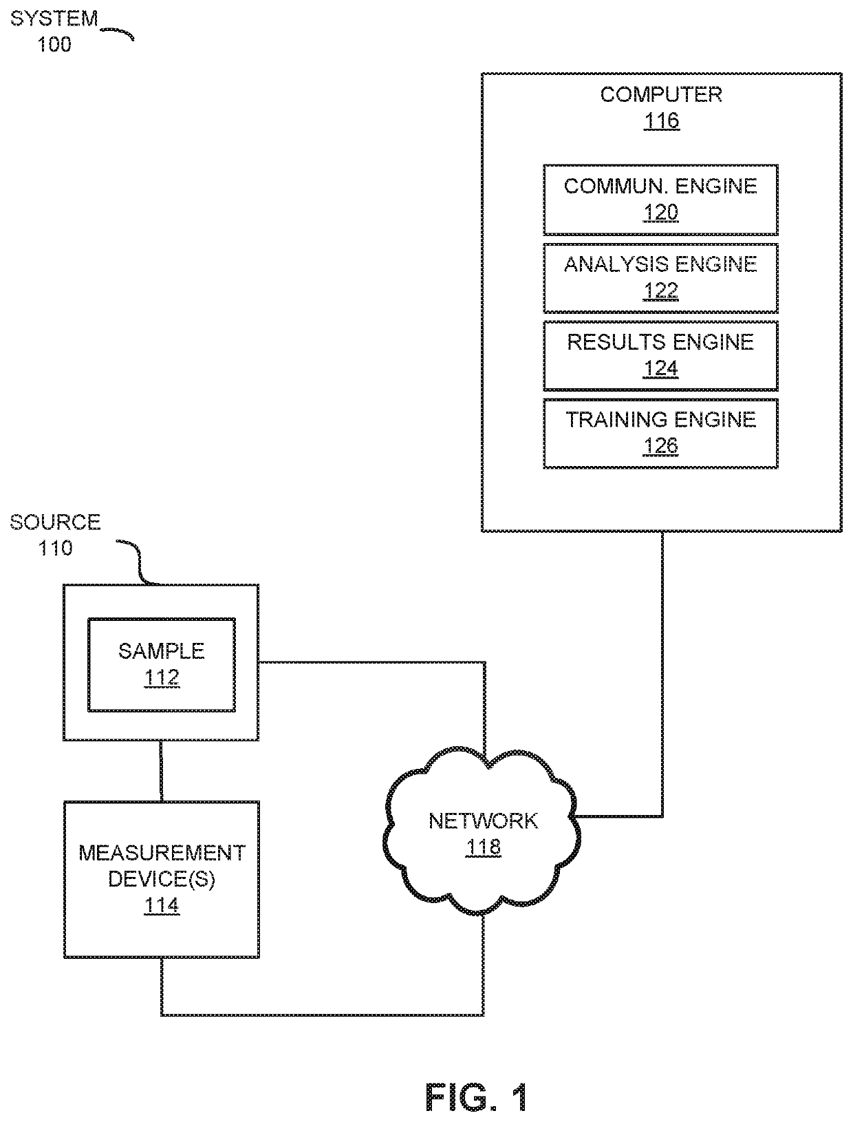
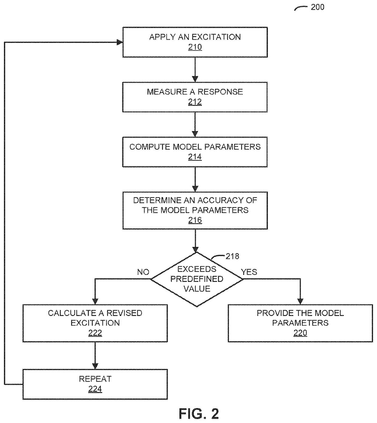
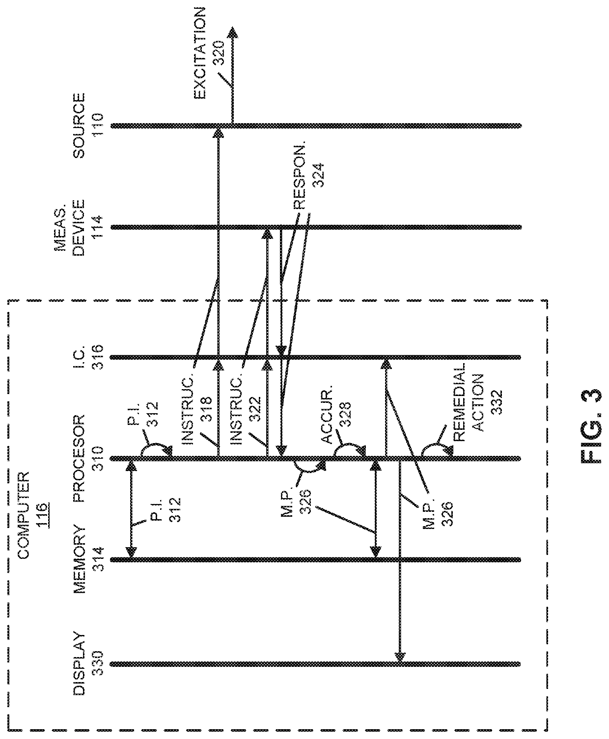
[0031]A system that determines model parameters associated with a sample is described. During operation, the system may measure, using a measurement device, a response associated with a sample to an excitation. Then, the system may compute, using the measured response and the excitation as inputs to one of an inverse model and a predetermined predictive model, model parameters on a voxel-by-voxel basis in a forward model with multiple voxels that represent the sample. The forward model may simulate response physics occurring within the sample to a given excitation, and the model parameters may include magnetic susceptibilities of the multiple voxels. Moreover, the system may determine an accuracy of the model parameters by comparing at least the measured response and a calculated predicted value of the response using the forward model, the model parameters and the excitation. When the accuracy exceeds a predefined value, the system may provide the model parameters as an output to: a...


PUM


Abstract

A system may measure, using a measurement device, a response associated with a sample to an excitation. Then, the system may compute, using the measured response and the excitation as inputs to one of an inverse model and a predetermined predictive model, model parameters on a voxel-by-voxel basis in a forward model with multiple voxels that represent the sample. The forward model may simulate response physics occurring within the sample to a given excitation, and the model parameters may include magnetic susceptibilities of the multiple voxels. Moreover, the system may determine an accuracy of the model parameters by comparing at least the measured response and a calculated predicted value of the response using the forward model, the model parameters and the excitation. When the accuracy exceeds a predefined value, the system may provide the model parameters as an output to: a user, another electronic device, a display, and / or a memory.

Description

CROSS-REFERENCE TO RELATED APPLICATION[0001]This application is a Continuation-in-Part of U.S. Non-Provisional application Ser. No. 16 / 277,939, entitled “Model Parameter Determination Using a Predictive Model,” by Jeffrey H. Kaditz, Jorge Villena and Athanasios Polymeridis, filed on Feb. 15, 2019, the contents of each of which are hereby incorporated by reference.BACKGROUNDField[0002]The described embodiments relate generally to determining model parameters associated with a sample for use in a forward model that simulates response physics of the sample to an excitation.Related Art[0003]Many non-invasive characterization techniques are available for determining one or more physical parameters of a sample. For example, magnetic properties can be studied using magnetic resonance or MR (which is often referred to as ‘nuclear magnetic resonance’ or NMR), a physical phenomenon in which nuclei in a magnetic field absorb and re-emit electromagnetic radiation. Moreover, density variations a...

Claims


Application Information

Patent Timeline
Patent Type & Authority Patents(United States)
IPC IPC(8): G01R33/30G01R33/36G01R33/44G01R33/54
CPCG01R33/30G01R33/36G01R33/443G01R33/54G01R33/5608
Inventor TAYLI, DORUKLEFKIMMIATIS, STAMATIOSPOLYMERIDIS, ATHANASIOS
Owner Q BIO INC
Why Eureka
Try Eureka