
Scaling for gain shape circuitry

a gain shape and circuit technology, applied in the field of signal processing, can solve the problems of poor audio quality, overlapped energy of one frame with (or “leak” into) another frame, and energy of one frame may occur between frames of the high-band, so as to reduce the energy difference

Active Publication Date: 2017-03-14
QUALCOMM INC
View PDF6 Cites 0 Cited by
  • Summary
  • Abstract
  • Description
  • Claims
  • Application Information

AI Technical Summary

Benefits of technology

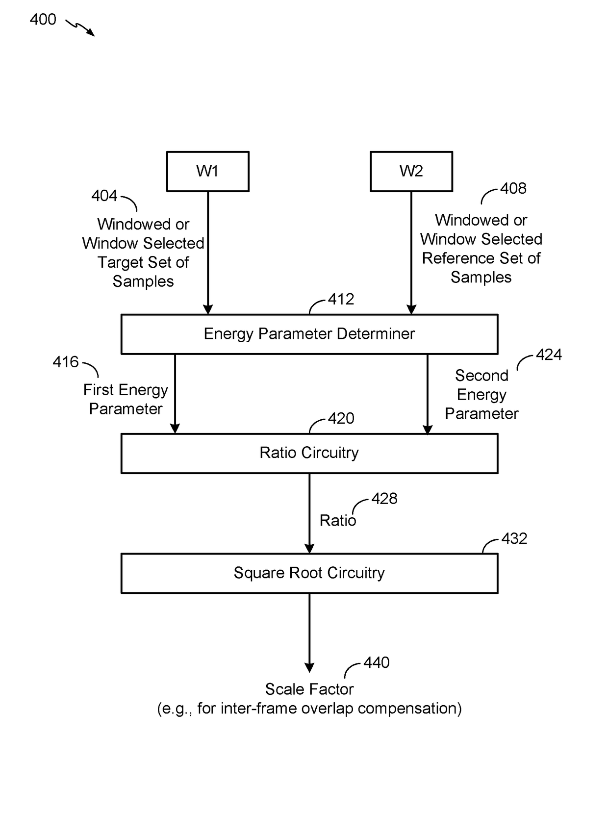
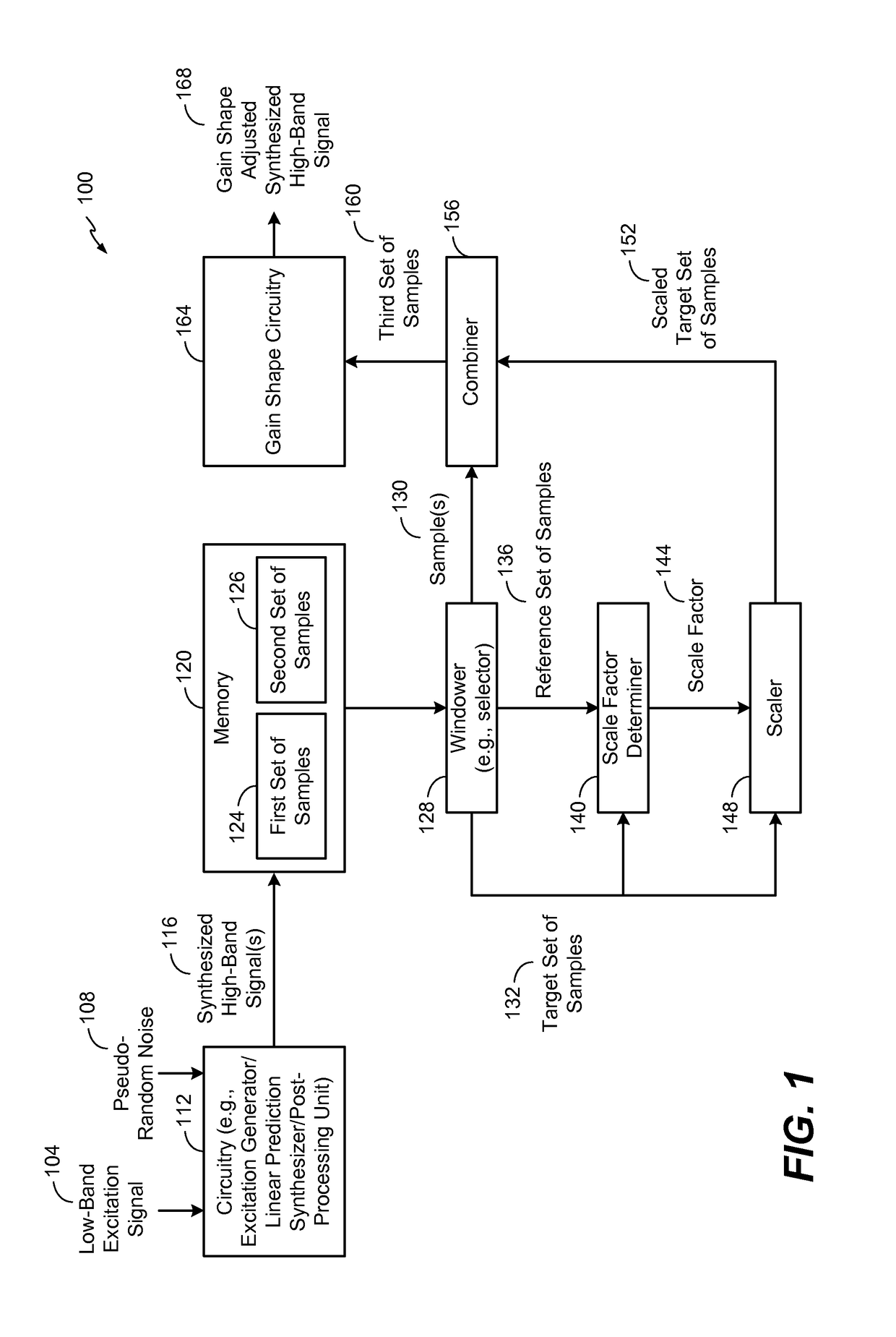
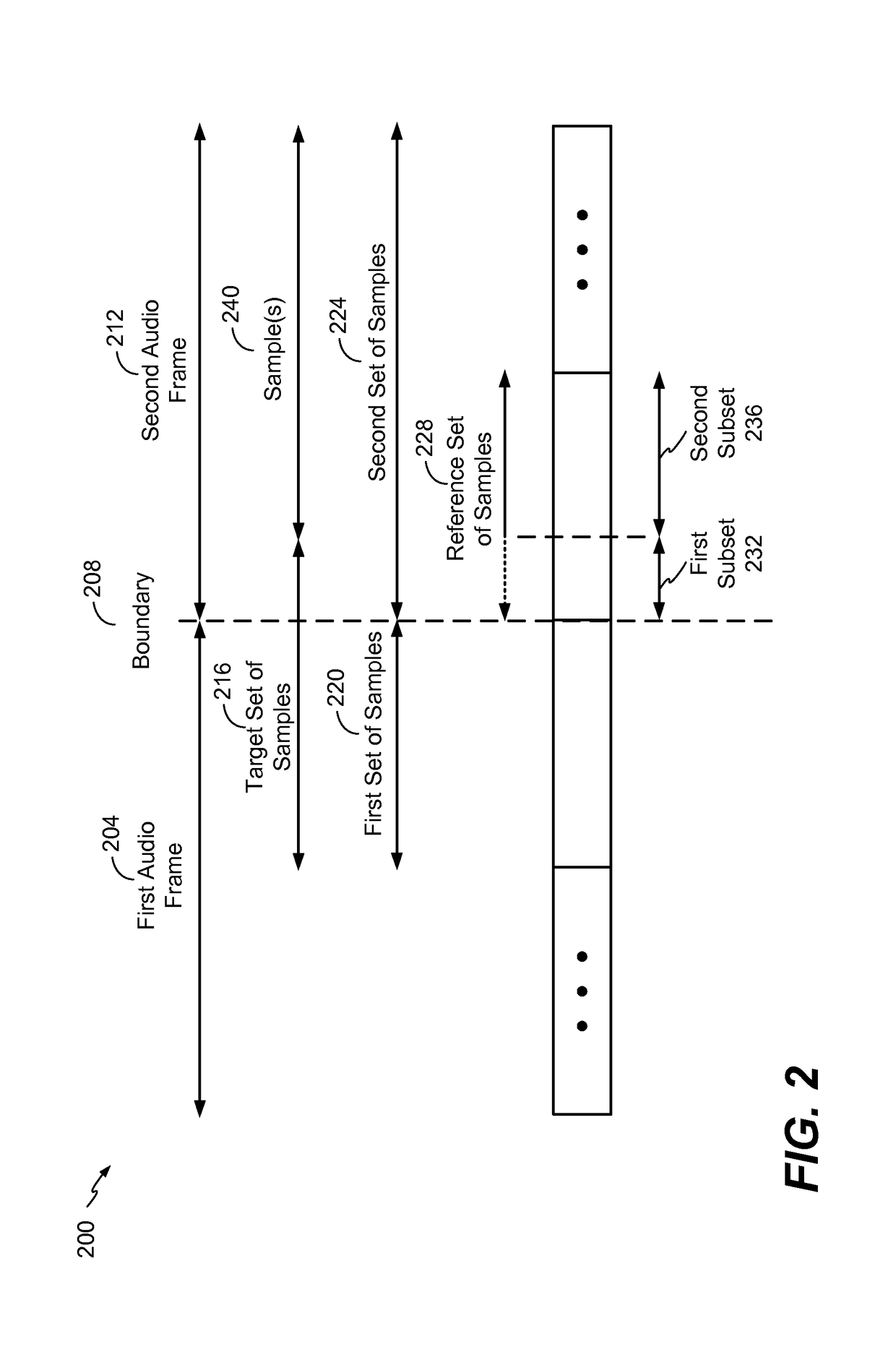
[0007]A device (such as a mobile device that communicates within a wireless communication network) may compensate for inter-frame overlap (e.g., energy “leakage”) between a first set of samples associated with a first audio frame and a second set of samples associated with a second audio frame by generating a target set of samples that corresponds to the inter-frame overlap. The device may also generate a reference set of samples associated with the second audio frame. The device may scale the target set of samples based on the reference set of samples, such as by reducing an energy difference between the target set of samples and the reference set of samples.
[0008]In an illustrative implementation, the device communicates in a wireless network based on a 3rd Generation Partnership Project (3GPP) enhanced voice services (EVS) protocol that uses gain shape circuitry to gain shape a synthesized high-band signal. The device may scale the target set of samples and “replace” the target set of samples with the scaled target set of samples prior to inputting the synthesized high-band signal to the gain shape circuitry, which may reduce or eliminate certain artifacts associated with the inter-frame overlap. For example, scaling the target set of samples may reduce or eliminate artifacts caused by a transmitter / receiver mismatch of a seed value (referred to as “bwe_seed”) associated the 3GPP EVS protocol.
[0013]One particular advantage provided by at least one of the disclosed embodiments is improved quality of audio reproduced at a receiving device, such as a wireless communication device that receives information corresponding to audio transmitted in a wireless network in connection with a telephone conversation. Other aspects, advantages, and features of the present disclosure will become apparent after review of the entire application, including the following sections: Brief Description of the Drawings, Detailed Description, and the Claims.

Problems solved by technology

In some circumstances, a “mismatch” of energy levels may occur between frames of the high-band.
However, some processing operations associated with encoding of frames performed by a transmitting device and synthesis of the frames at a receiving device may cause energy of one frame to overlap with (or “leak” into) another frame.
As a result, certain decoding operations performed by a receiving device to generate (or predict) the high-band may cause artifacts in a reproduced audio signal, resulting in poor audio quality.

Method used


Image

  • Scaling for gain shape circuitry
  • Scaling for gain shape circuitry
  • Scaling for gain shape circuitry

Examples


example 1

[0072]

prev_energy = 0;curr_energy = 0;for(i = 0; i {  if(i  else w1(n) = 0;  if(i>=30 && i  else w2(n) = 0;}for(i = 0; i {  prev_energy +=(w1[i]*synthesized_high_band[i])*(w1[i]*synthesized_high_band[i]); / *0-29* /   curr_energy +=(w2[i+30]*synthesized_high_band[i+30])*(w2[i+30]*synthesized_high_band[i+30]); / *30-59* / }scale_factor = sqrt(curr_energy / prev_energy);if ((prev_energy )==0) scale_factor = 0;for( i=0; i{  actual_scale = scale_factor;  shaped_shb_excitation[i] =actual_scale*synthesized_high_band[i];}for( ; i{  temp = (i−19) / 10.0f;   / *tapering* /   actual_scale = (temp*1.0f + (1.0f−temp)*scale_factor);  shaped_shb_excitation[i] =actual_scale*synthesized_high_band[i];}

[0073]Example 2 illustrates an alternative pseudo-code which may be executed in connection with non-overlapping windows. For example, the graph 310 of FIG. 3 illustrates that the first window w1(n) and the second window w2(n) may be non-overlapping. One or more scaling operations described with reference to Example 2 ...

example 2

[0074]

L_SHB_LAHEAD = 20;    prev_pow = sum2_f( shaped_shb_excitation,L_SHB_LAHEAD + 10 );    curr_pow = sum2_f( shaped_shb_excitation +L_SHB_LAHEAD + 10, L_SHB_LAHEAD + 10 );    if( voice_factors[0]> 0.75f )    {      curr_pow *= 0.25;    }    if( prev_pow == 0 )    {      scale = 0;    }    else    {      scale = sqrt( curr_pow / prev_pow );    }    for( i=0; i    {      shaped_shb_excitation[i] *= scale;    }    for( ; i    {      temp = (i−19) / 10.0f;      shaped_shb_excitation[i] *= (temp*1.0f + (1.0f−temp)*scale);    }

[0075]In Example 2, the function “sum2_f” may be used to calculate the energy of a buffer input as the first argument to the function call, for a length of the signal input as the second argument to the function call. The constant L_SHB_LAHEAD is defined to take a value of 20. This value of 20 is an illustrative non-limiting example. The buffer voice factors holds the voice factors of the frame calculated one for each sub-frame. Voice factors are an indicator of the...


PUM


Abstract

A method of operation of a device includes receiving a first set of samples and a second set of samples. The first set of samples corresponds to a portion of a first audio frame and the second set of samples corresponds to a second audio frame. The method further includes generating a target set of samples based on the first set of samples and a first subset of the second set of samples and generating a reference set of samples based at least partially on a second subset of the second set of samples. The method also includes scaling the target set of samples to generate a scaled target set of samples and generating a third set of samples based on the scaled target set of samples and one or more samples of the second set of samples.

Description

I. CROSS-REFERENCE TO RELATED APPLICATION(S)[0001]This application claims the benefit of U.S. Provisional Patent Application No. 62 / 105,071, filed Jan. 19, 2015 and entitled “SCALING FOR GAIN SHAPE CIRCUITRY,” the disclosure of which is incorporated by reference herein in its entirety.II. FIELD[0002]This disclosure is generally related to signal processing, such as signal processing performed in connection with wireless audio communications and audio storage.III. DESCRIPTION OF RELATED ART[0003]Advances in technology have resulted in smaller and more powerful computing devices. For example, there currently exist a variety of portable personal computing devices, including wireless computing devices, such as portable wireless telephones, personal digital assistants (PDAs), and paging devices that are small, lightweight, and easily carried by users. More specifically, portable wireless telephones, such as cellular telephones and Internet Protocol (IP) telephones, can communicate voice ...

Claims


Application Information

Patent Timeline
Patent Type & Authority Patents(United States)
IPC IPC(8): G10L21/038G10L19/083G10L19/032
CPCG10L19/083G10L19/032G10L21/038
Inventor CHEBIYYAM, VENKATA SUBRAHMANYAM CHANDRA SEKHARATTI, VENKATRAMAN S.
Owner QUALCOMM INC
Learn More