Variable pitch rotor blade with double flexible retention elements

a technology of flexible retention elements and rotor blades, which is applied in the direction of rotors, marine propulsion, vessel construction, etc., can solve the problems of significant twisting or turning forces, blades that are inclined towards undesirable flat pitch positions, rotor overspeed conditions, and potential blade loss, so as to reduce the drastic response of the device, reduce the power-producing capacity of the propulsive device, and reduce the effect of ctm forces

Active Publication Date: 2009-04-09
AEROCOMPOSITES +1
View PDF4 Cites 8 Cited by
  • Summary
  • Abstract
  • Description
  • Claims
  • Application Information

AI Technical Summary

Benefits of technology

[0012]One advantage of the present invention is that the thrust-producing and / or power-absorbing capacity of a propulsive device is more easily controlled because dual support of the rotor blade helps balance high CTM forces. The reduction derives from alignment of the blade mass elements from the forward and aft portions of the airfoil with each respective support member, and / or the positioning of the attachment points of these members to create a desirable restoring, twisting force when centrifugal load is applied. In general, these support members tend to follow an extension of the natural cumulative twist built into each airfoil required to align airfoil sections with local airflow vectors along the length of the blade. Changes in rotor operating conditions (e.g., variations in air velocity entering the rotor, the level of power applied to the rotor, and the like) can be compensated for or controlled to limit drastic responses of the device. For example, a rotor propelling an aircraft can experience or require significant changes in velocity and operating power between static thrust operations, take-offs, climbs, cruise conditions, and descent conditions. By varying the pitch of the rotor blades accordingly, efficiency (e.g., fuel economy) and responsiveness of the device can be realized.
[0013]A primary advantage for propellers is that high blade centrifugal forces can be efficiently supported by a much smaller, compact, central inner hub. The outer hub is thus lightly loaded, supporting mainly the blade bending and thrust loads while providing a pivot center about which the blade can turn when changes in pitch are commanded by the pitch control system. As such the outer hub can be constructed as a thin, lightweight structure of various low cost materials.
[0014]Another advantage for both propellers and fan applications is that the need for a counterweight on each blade as a pitch control backup system is eliminated. Without the counterweights, additional loading of the rotor hub and bearings is eliminated, thereby reducing the size and amount of wear to the device. Furthermore, without a counterweight, the risk of failure of the associated retention mechanisms is eliminated, which in turn removes the possibility of impact damage resulting therefrom as well as rotor unbalance conditions.
[0015]Still another advantage for both propellers and fans is that a structurally efficient means of blade attachment is realized. Blade attachment using this means is especially well-suited to the design and fabrication of thin, efficient, lightweight, composite rotor blades.
[0016]Still another advantage for fan designs is derived from the calculated frangibility of a post and / or mating receptacle on which the rotor blade pivots. By being calculated to fail under excessive loading from blade impact with foreign objects (e.g., from the development of abnormally large loads such as from the ingestion of birds, runway debris, or other foreign objects), the blade is allowed to swing more freely without fracture of the support members. Thus blade loss and extreme unbalance conditions may be mitigated.

Problems solved by technology

A further complication is that substantial centrifugal loads on the plate-like structures of the blades themselves also produce significant twisting or turning forces that pitch control systems must overcome.
These forces tend to turn the blade towards an undesirable flat pitch position.
In the event that a malfunction of the pitch control system occurs, the forces acting on the blades could turn the blades to the flat pitch position, reducing rotor rotational resistance, thereby resulting in rotor overspeed conditions and potential blade loss.
In other words, in an oblong airfoil having a non-circular, non-symmetrical cross section, the mass about the pitch change axis is not evenly distributed, and centrifugal forces originating from the rotor's axis of revolution and acting on elements of the airfoil cause inertial twisting forces.
However, if there is a malfunction and / or loss of control of the pitch control system (e.g., due to loss of engine power), a rotor blade will naturally turn toward lower pitch.
Because low pitch results in less rotational resistance for the engine, the situation can result in an undesirable overspeed of the rotor and engine.
In extreme conditions in variable pitch systems with no low pitch stop, the TTM can turn the blades to low pitch, and rotor thrust can suddenly switch to a high drag force that can cause possible loss of aircraft control and / or result in rotor overspeed.
In a single engine aircraft, increased drag can limit glide distance for an unplanned landing, while in a twin engine configuration, the asymmetric drag of one disabled propulsor can hinder the ability of the pilot to control the aircraft.
These weights have also been known to be substantial in mass, thereby adding unsprung weight to the rotor blades and further loading the bearings associated with the rotor hub and blade retention mechanisms.
Also, these weights often have associated retention mechanisms or other devices that may be prone to failure under normal operating conditions due to the mechanical stresses encountered.
If a failure is experienced, the high energy of the released mass may result in impact damage as well as high rotor unbalance conditions.
In at least some of these systems, if the pitch of the rotor blades is maintained in a less than optimum position for gliding (in an aircraft having a single engine configuration) or for compromised operation (in an aircraft having a twin engine configuration), increased drag forces may be generated which inhibit the ability of an operator to properly manage the system.

Method used


Image

  • Variable pitch rotor blade with double flexible retention elements
  • Variable pitch rotor blade with double flexible retention elements
  • Variable pitch rotor blade with double flexible retention elements

Examples


Embodiment Construction

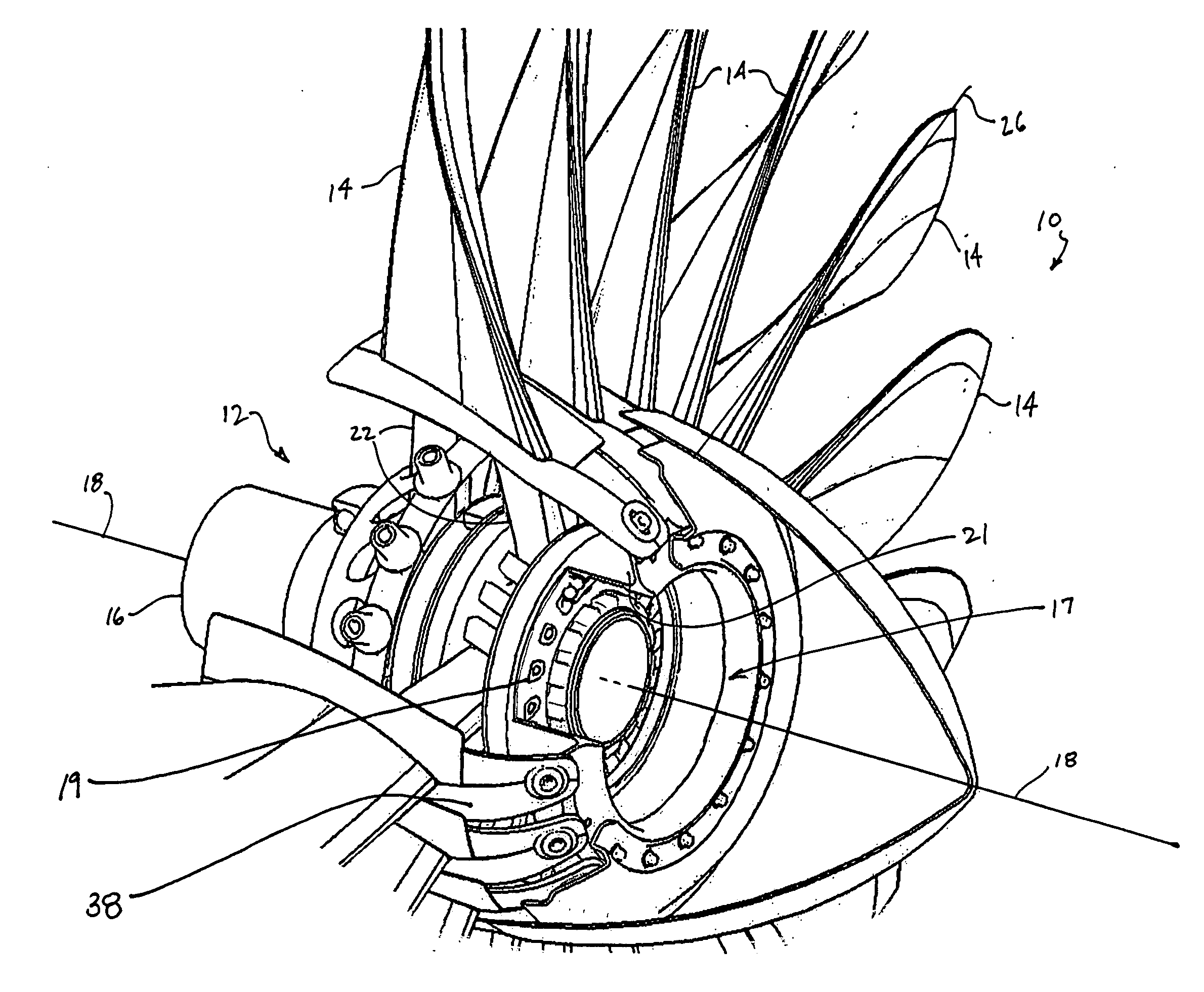
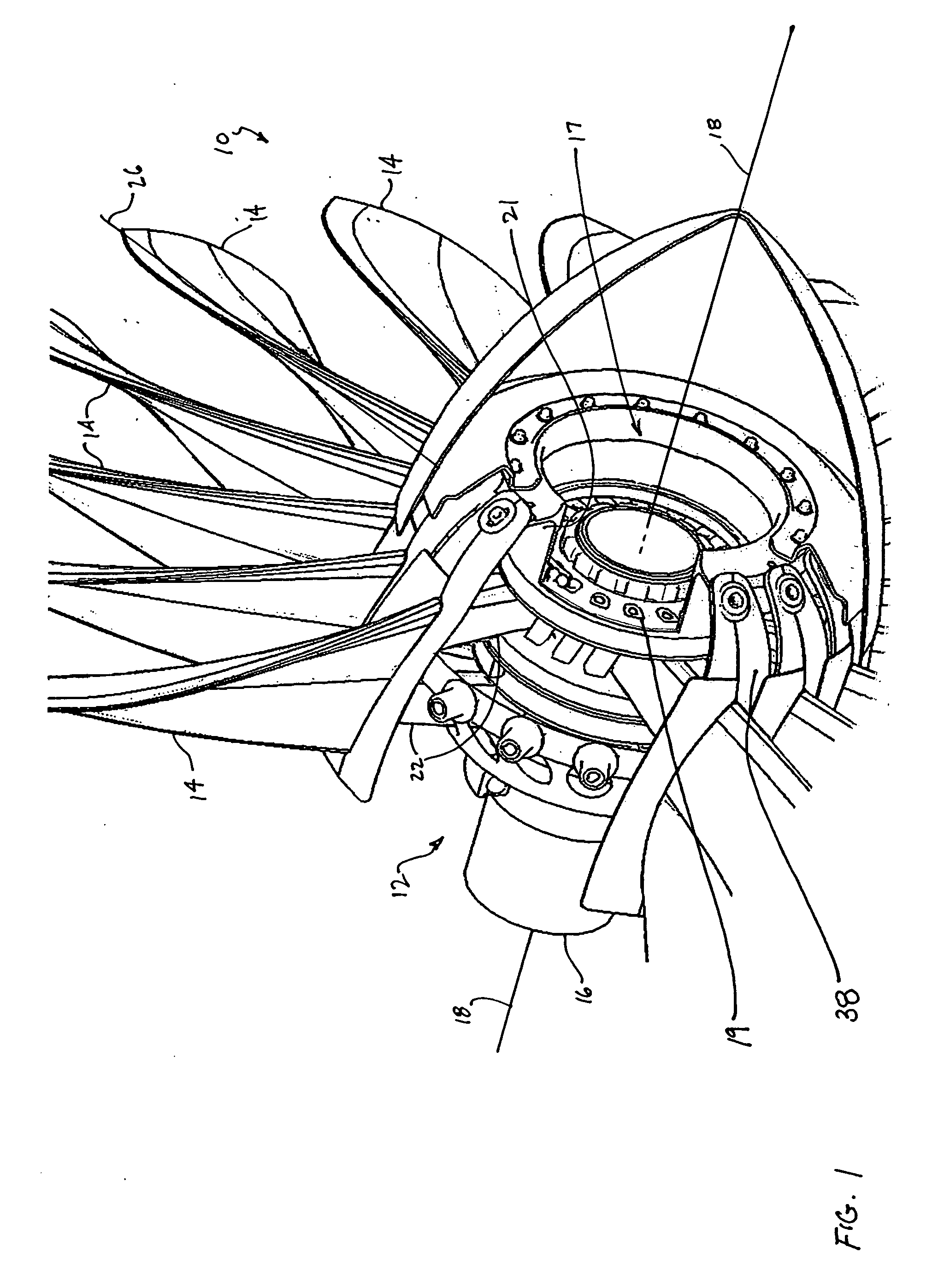
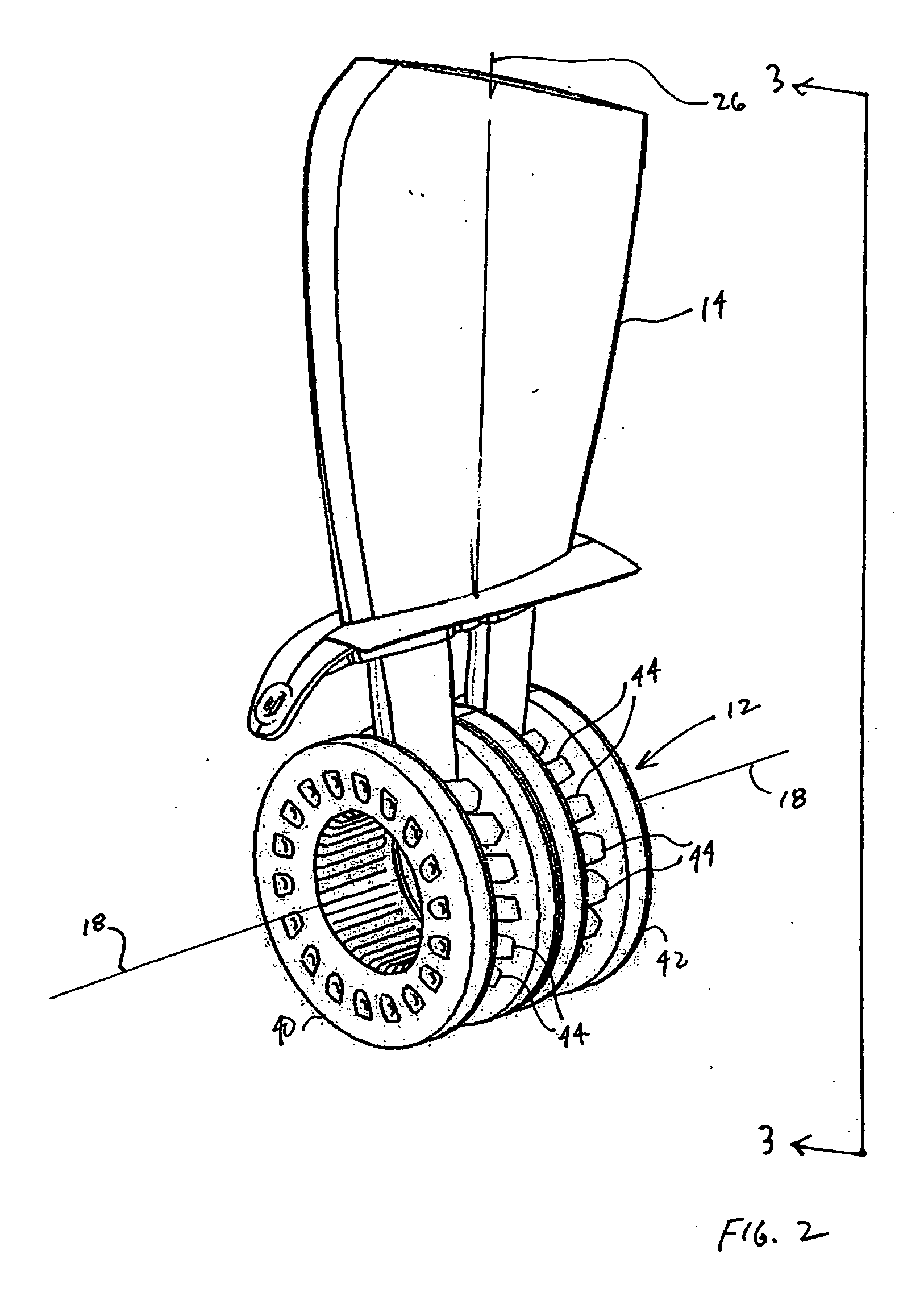
[0030]The present invention utilizes a configuration of associated independently controllable support members to vary the positions of rotor blades. Although only two support members are shown for each rotor blade, it should be understood that any number of support members may be used to control a rotor blade. In propulsive thrust devices, the positions of the rotor blades are variable primarily to optimize the angular orientation of part or all of the airfoil surface relative to local air flow direction(s) along the length of a rotor blade developing propulsive thrust. Because the air flow direction changes with operating condition, adjustment of blade pitch angle can provide significant increases in propulsive efficiency resulting in greater fuel economy. Although the propulsive thrust devices referred to herein are referred to as aircraft engines, it should be understood that any type of device having a rotating blade is within the scope of the present invention.

[0031]Referring t...


PUM


Abstract

A propulsive thrust device for an engine includes a rotor blade and a hub assembly on which the rotor blade is mounted. The rotor blade comprises an airfoil and at least two support members. A propeller thrust device includes a rotor blade, a central hub at which the rotor blade centrifugal load is supported, and an outer hub supporting a control mechanism mechanically connected to the rotor blade and controllable to vary the pitch of the rotor blade on the central hub. A rotor blade for an aircraft engine or in a separate ducted fan housing driven by a powered shaft or gearbox output shaft includes an airfoil and first and second support members attached to the airfoil. An extended arm or portion of the structure at the root of the airfoil of each blade is attached to a controllable mechanism that can vary the pitch of all blades simultaneously.

Description

CROSS REFERENCE TO RELATED APPLICATION[0001]This application claims the benefits of U.S. Provisional Patent Application Ser. No. 60 / 651,089, filed on Feb. 7, 2005, the contents of which are incorporated herein by reference in their entirety.TECHNICAL FIELD[0002]This invention relates in general to rotor blades and, more particularly, to rotor blades for propulsive thrust devices in aircraft engines in which the rotor blades can be varied in pitch to control thrust-producing and / or power-absorbing capacities of such devices.BACKGROUND OF THE INVENTION[0003]Standard configurations of rotor blades typically used in aircraft rotary propulsion systems that allow variable pitch operation usually include a root attachment mechanism such as a ball / roller bearing and / or flex member, both of which allow pitch change of the blade with relatively low friction between components. To impart the necessary structural integrity to such mechanisms (e.g., to accommodate the substantial centrifugal for...

Claims


Application Information

Patent Timeline
Patent Type & Authority Applications(United States)
IPC IPC(8): F01D7/00F01D5/30
CPCB64C11/06
Inventor VIOLETTE, JOHN A.
Owner AEROCOMPOSITES
Why Eureka
Try Eureka