
Method for quantitative evaluation of fluid pressures and detection of overpressures in an underground medium

a fluid pressure and fluid detection technology, applied in seismology for waterlogging, instruments, reradiation, etc., can solve the problems of stress redistribution, fracture re-opening or possibly initiating hydraulic fracturing, and the presence of overpressure zones under exploration can have serious financial and sometimes human consequences,

Inactive Publication Date: 2009-04-09
INST FR DU PETROLE
View PDF2 Cites 19 Cited by
  • Summary
  • Abstract
  • Description
  • Claims
  • Application Information

AI Technical Summary

Benefits of technology

The invention relates to a method for evaluating fluid pressures in an underground zone using seismic data and well data. The method involves defining an analysis interval, performing a pre-Stack stratigraphic inversion of the seismic data to construct a seismic impedance cube, determining a lithoseismic facies cube, and calculating differential pressures and confining pressures. The method can be used to detect overpressure zones and modify drilling conditions accordingly. It also allows for the evaluation of fluid pressures at depths not yet reached by the wellbore. The invention provides a more accurate and reliable means for evaluating fluid pressures in underground zones.

Problems solved by technology

The presence of overpressure zones under exploration can have serious financial and sometimes human consequences during drilling if the fluid pressures are not known.
In fact, in the sphere of exploration, the fluid pressure can be close to the minimum principal stress and induce the re-opening of fractures or possibly initiate hydraulic fracturing.
Finally, depletion in overpressure zones can induce notable stress redistributions, possibly with great consequences on the productivity of reservoirs.
However, the conventionally used seismic processings of velocity analysis type (Yilmaz, 1987) have a limited efficiency (Pennebaker, 1968, Grauls et al., 1995), mainly because, on the one hand, of their spatial resolution, too weak to be efficiently used for drilling and, on the other hand, because they do not take sufficiently into account the lithologic variations (Reynolds, 1970), often critical in overpressure phenomena.
The main problems of these methods are, on the one hand, the relatively low spatial resolution of the conventional methods that make them difficult to use for drilling operations.
The second problem is the implicit assumption according to which any anomalic velocity change is attributed to an overpressure, while dismissing for example causes such as the lithology change (Reynolds, 1970, for example).

Method used


Image

  • Method for quantitative evaluation of fluid pressures and detection of overpressures in an underground medium
  • Method for quantitative evaluation of fluid pressures and detection of overpressures in an underground medium
  • Method for quantitative evaluation of fluid pressures and detection of overpressures in an underground medium

Examples


Embodiment Construction

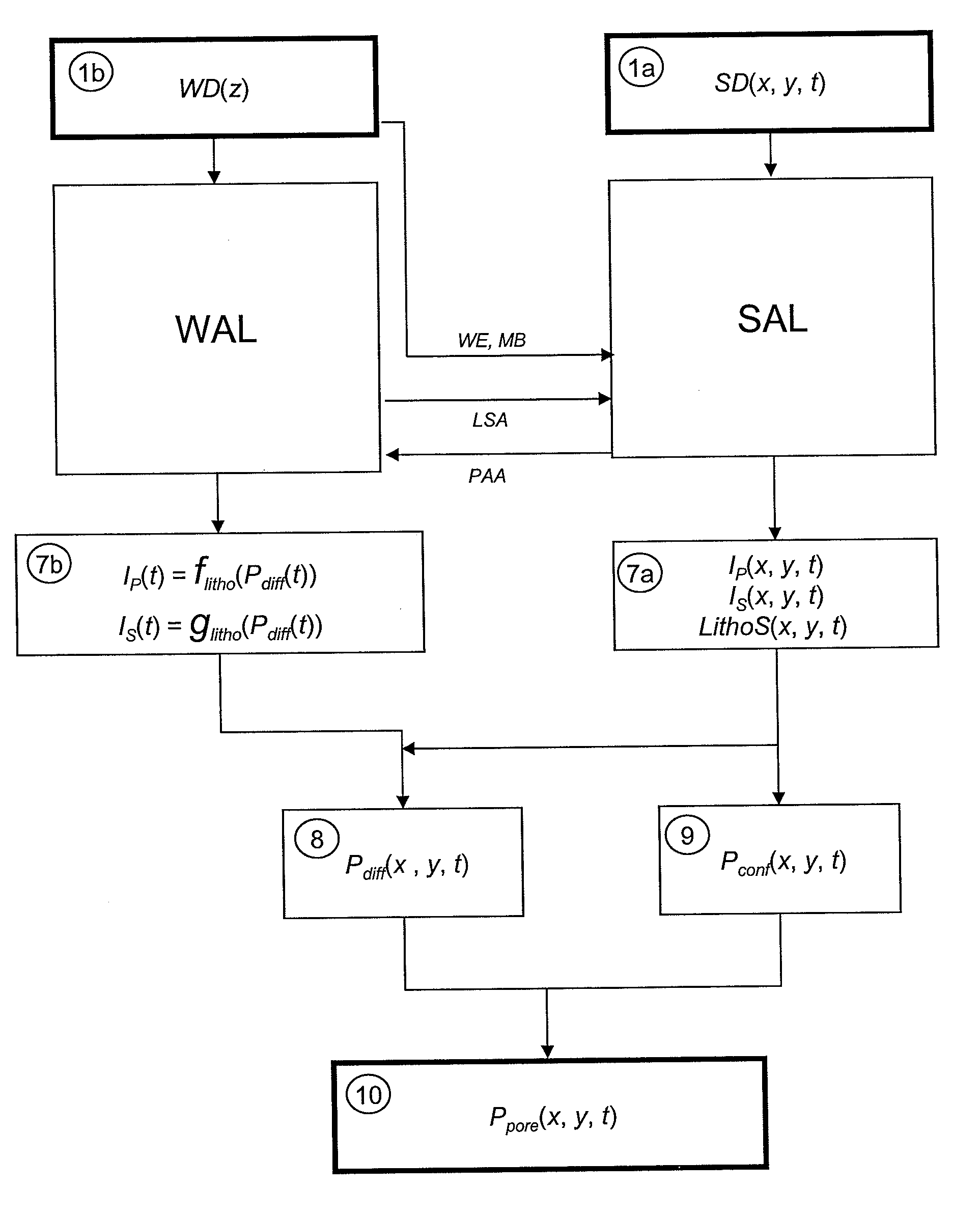
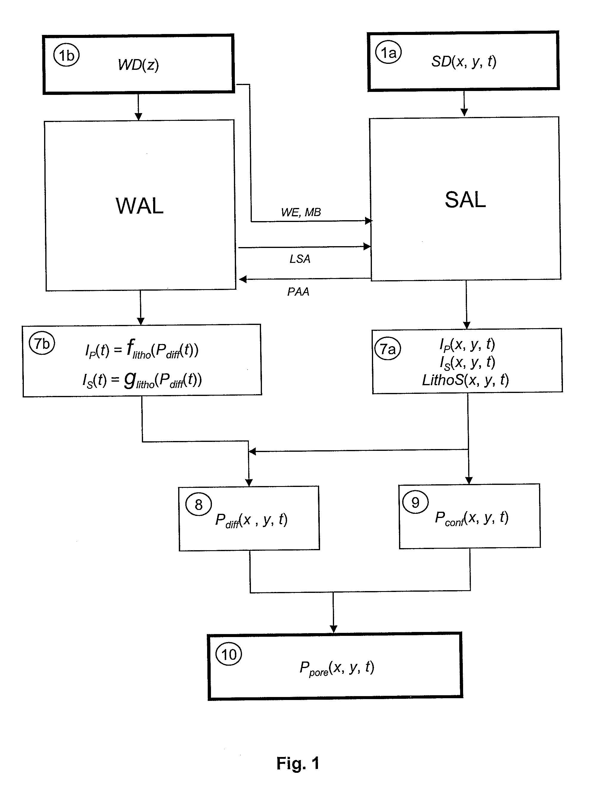
[0054]The method allows to evaluate the fluid pressures of an underground zone from well data and seismic data. It mainly comprises the following six stages:

[0055]1) Defining time analysis intervals.

[0056]2) Processing the seismic data over each analysis interval: seismic impedance cubes and lithoseismic facies cube.

[0057]3) Processing the well data over each analysis interval: petro-acoustic relation between seismic impedance in wells and differential pressure in wells.

[0058]4) Determining a differential pressure cube (Pdiff(x,y,t)).

[0059]5) Determining a confining pressure cube (Pconf(x,y,t)).

[0060]6) Determining a fluid pressure cube (Ppore(x,y,t)).

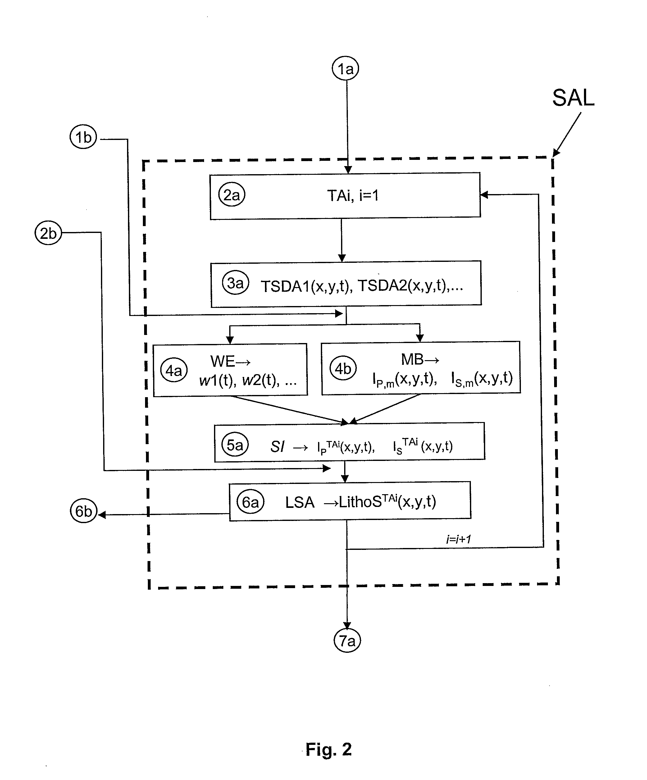
[0061]The various stages of the method are diagrammatically shown in FIGS. 1 to 3. FIG. 1 is a general illustration of the various stages of the method. As described more in detail below, these stages consist of two interconnected subsets of stages, i.e., on the left side of the figure, the stages corresponding to the well data process...


PUM


Abstract

Method for evaluating fluid pressures in an underground zone by means of seismic and well data. The zone studied is divided into several time analysis intervals. For each of these intervals, a pre-stack stratigraphic inversion of the seismic data is then carried out using geological a priori information, and a lithoseismic facies cube is determined by lithoseismic analysis. Then, for each facies, relations connecting the seismic impedances of wells to differential pressures in wells are determined in each analysis interval. Finally, a differential pressure cube is determined using the previous relations, as well as a confining pressure cube, in order to determine the fluid pressures in the subsoil by simple difference between these two cubes. Application: petroleum sphere for the detection of overpressure zones during drilling for example.

Description

FIELD OF THE INVENTION[0001]The present invention relates to a method for quantitative evaluation of fluid pressures in the subsoil with a good spatial resolution by means of seismic and well data by taking into account the geological varieties of the media crossed.[0002]The method can be used in the petroleum sphere for the detection of overpressure zones for drilling.BACKGROUND OF THE INVENTION[0003]The following documents, mentioned in the description hereafter, illustrate the state of the art:[0004]Barnola, A. S., Andrieux B., Tonellot T., Voutay O., 2003, Pre-stack stratigraphic inversion and attribute analysis for optimal reservoir characterisation, 73rd Ann. Internat. Mtg: Soc. of Expl. Geophys., 1493-1496, Dallas.[0005]Bertrand, C., Tonellot T., Fournier F., 2003, Seismic facies analysis applied to P and S impedances from pre-stack inversion, 72nd Ann. Internat. Mtg: Soc. of Expl. Geophys., 217,220.[0006]Bourbié, T., Coussy, O., Zinszner, B., 1987, Acoustics of porous media,...

Claims


Application Information

Patent Timeline
Patent Type & Authority Applications(United States)
IPC IPC(8): G01V1/30
CPCG01V1/306
Inventor RASOLOFOSAON, PATRICKTONELLOT, THIERRY
Owner INST FR DU PETROLE
Learn More