
Laser cladding device with an improved nozzle

a technology of laser cladding and nozzle, which is applied in the direction of electrostatic spraying apparatus, coatings, ion implantation coatings, etc., can solve the problems of significant amount of powdered metal directed at the weld zone actually escaping the process, and the known nozzles for laser cladding assemblies are limited, so as to achieve high quality and reduce the effect of powder catchment and low cos

Active Publication Date: 2009-04-16
WHITFIELD RONALD PETER
View PDF6 Cites 46 Cited by
  • Summary
  • Abstract
  • Description
  • Claims
  • Application Information

AI Technical Summary

Benefits of technology

"The present invention is a laser cladding device that can apply a coating to a part. It includes a laser, a main body, a laser light channel, a coating channel, and a vacuum channel and nozzle. The nozzle has a delivery port, a coating port, and a vacuum port. In operation, the vacuum port creates a vacuum, pulling the coating towards the part. The invention has several advantages, including high-quality and low-cost construction, and improved powder catchment."

Problems solved by technology

Known nozzles for laser cladding have various levels of complexity.
However, such known nozzles for laser cladding assemblies are limited in that the majority of the gas flow is deflected away from the laser weld zone.
Therefore a significant amount of the powdered metal directed at the weld zone actually escapes the process altogether.

Method used


Image

  • Laser cladding device with an improved nozzle
  • Laser cladding device with an improved nozzle
  • Laser cladding device with an improved nozzle

Examples


Embodiment Construction

[0017]It will be apparent to those skilled in the art, that is, to those who have knowledge or experience in this area of technology, that many uses and design variations are possible for the laser cladding device disclosed here. The following detailed discussion of various alternative and preferred features and embodiments will illustrate the general principles of the invention with reference to a laser cladding device suitable for use in the manufacture of metal parts with enhanced metallurgical properties. Other embodiments suitable for other applications will be apparent to those skilled in the art given the benefit of this disclosure.

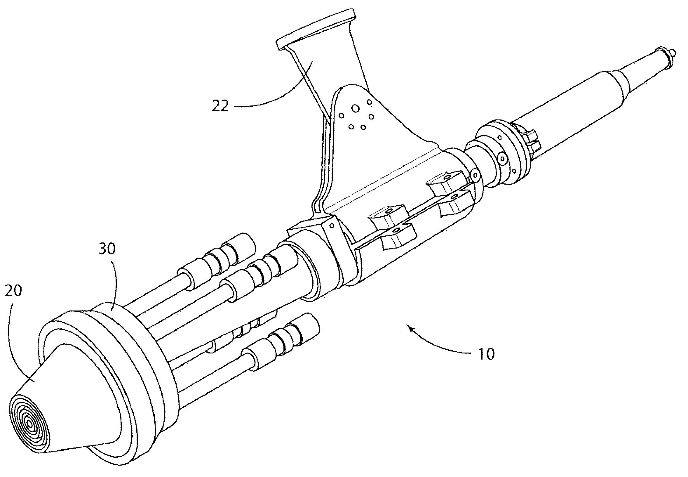
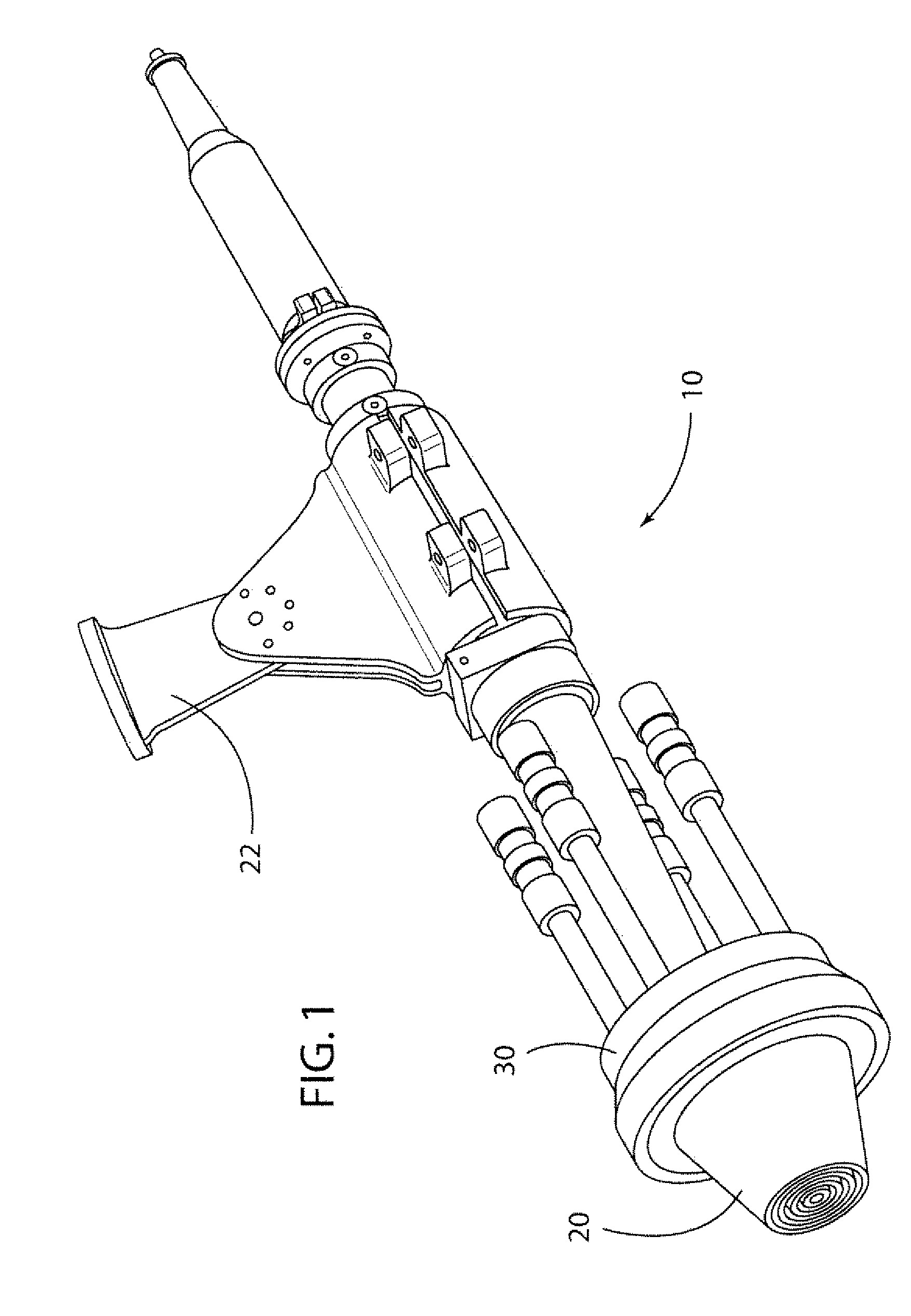
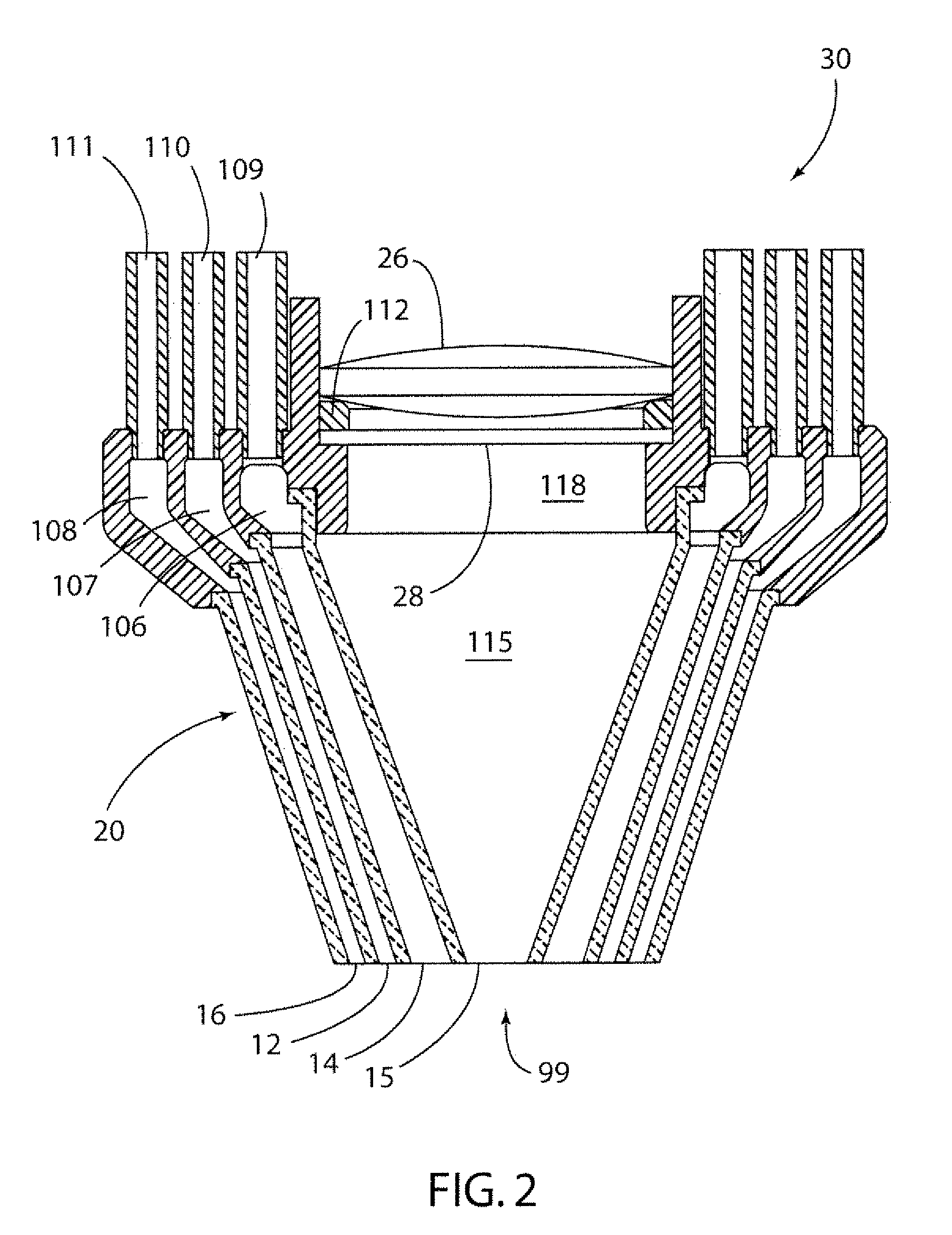
[0018]Turning now to the drawings, FIG. 1 shows a portion of a laser cladding device 10 in accordance with a preferred embodiment. The device is adjustably mounted via manipulator arm 22 connected to main body 30. A nozzle 20 is attached to the main body. The nozzle 20 and main body 30 are preferably formed as separate components, but could be form...


PUM

PropertyMeasurementUnit
thicknessesaaaaaaaaaa
heataaaaaaaaaa
vacuumaaaaaaaaaa

Abstract

A laser cladding device for applying a coating to a part comprising a laser which can generate laser light, which is adapted to heat the coating and the part, a main body defining a laser light channel adapted to transmit the laser light to the part, a coating channel adapted to transmit the coating to the part, and a vacuum channel and a nozzle having an exit. The nozzle comprises a delivery port at one end of the laser light channel, a coating port at one end of the coating channel, and a vacuum port at one end of the vacuum channel, wherein the vacuum port is positioned generally adjacent the delivery port In operation the vacuum port draws a vacuum, pulling the coating towards the part.

Description

RELATED APPLICATION[0001]This application claims priority benefit of U.S. provisional patent application No. 60 / 998,188 filed on Oct. 10, 2007.FIELD OF THE INVENTION[0002]The present invention relates to the field of laser cladding, and more particularly to the laser cladding devices having an improved nozzle.BACKGROUND OF THE INVENTION[0003]Laser cladding by powder metal injection is used in manufacturing, component repair, rapid prototyping and coating. A laser beam travels down a passage to exit out a port in focused alignment with a flow of powdered metal, typically a conical flow around the laser. The laser melts both a thin layer of a surface of a part and the metal powder introduced to the surface, allowing the molten powdered metal to fuse with the surface of the part. This technique is well know for producing parts with enhanced metallurgical qualities such as a superior coating with reduced distortion and enhanced surface quality. Layers of various thicknesses can be forme...

Claims


Application Information

Patent Timeline
Patent Type & Authority Applications(United States)
IPC IPC(8): C23C14/24
CPCC23C26/02B05B7/228B05B1/24B05D1/12B05D1/16B22F3/105C23C24/10
Inventor WHITFIELD, RONALD PETER
Owner WHITFIELD RONALD PETER
Learn More