
Circulation Type Conveying Device

a conveying device and circulation type technology, applied in the direction of table equipment, service system furniture, domestic applications, etc., can solve the problem of taking a lot of time and effort to transport and install the equipment inside the restauran

Inactive Publication Date: 2009-04-16
ISHINO SEISAKUSHOKK
View PDF5 Cites 0 Cited by
  • Summary
  • Abstract
  • Description
  • Claims
  • Application Information

AI Technical Summary

Benefits of technology

[0005]The present invention is aiming to solve these problems and provide a circulation type conveying device easily transportable, easily assembled in installation, and useful for a user by projecting tables.Means for Solving the Problems
[0011]In the above aspect, the carried articles being conveyed by the carrying unit can be stored within the storage box, and when the storage box is removed from the base, the tables can close the upper side opening without no difficulty. Moreover, when the storage box is mounted on the base, the movement of the carrying unit towards this storage box will be deterred by the storage box itself. Accordingly, no other means for restricting the carrying unit's movement is necessary.
[0013]In the above aspect, the pair of tables can open and close the opening from both sides and so the moving distance of the tables for obtaining a predetermined area of the opening is shorter than the moving distance of only one table.
[0017]In the above aspect, when the carrying unit is placed on the base, the connecting means of the carrying unit is automatically connected with a driving means and so it takes short time to assemble the circulation type conveying device.
[0019]In the above aspect, after the carrying unit's setting position on the base is decided, the connecting means is connected with the driving means. Then the connection is able to be ensured, and the damage to the connection part from location gap etc. is prevented.

Problems solved by technology

Nevertheless, regardless how small this circulation type conveying device might be, it is an all-in-one base and tables and carrying unit, and so it takes a lot of time and effort to transport and install it inside a restaurant.

Method used


Image

  • Circulation Type Conveying Device
  • Circulation Type Conveying Device
  • Circulation Type Conveying Device

Examples


embodiments

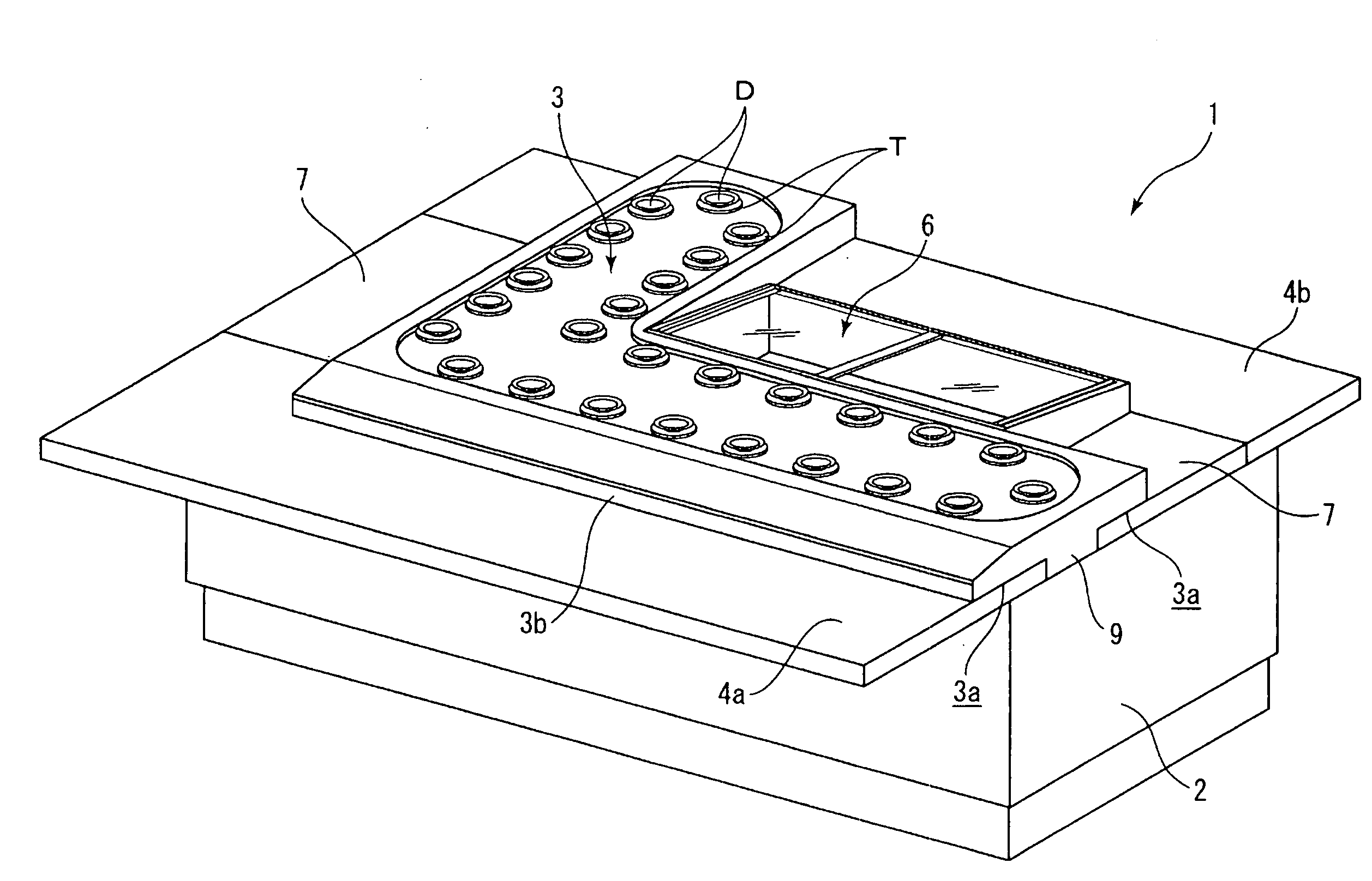
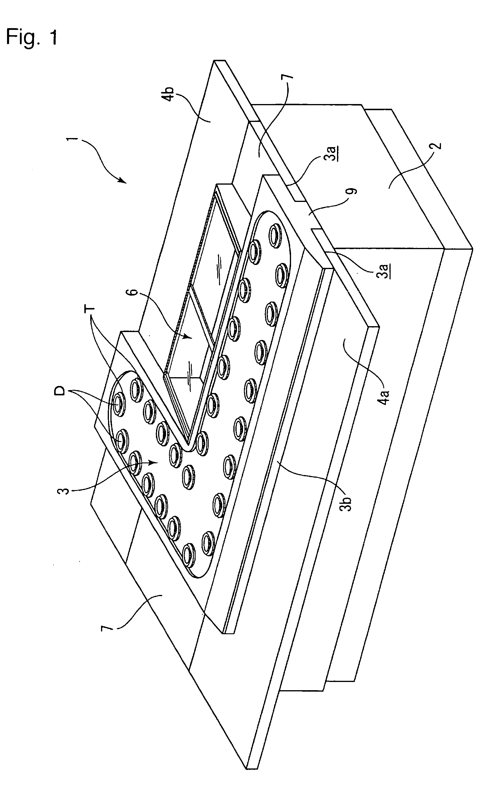
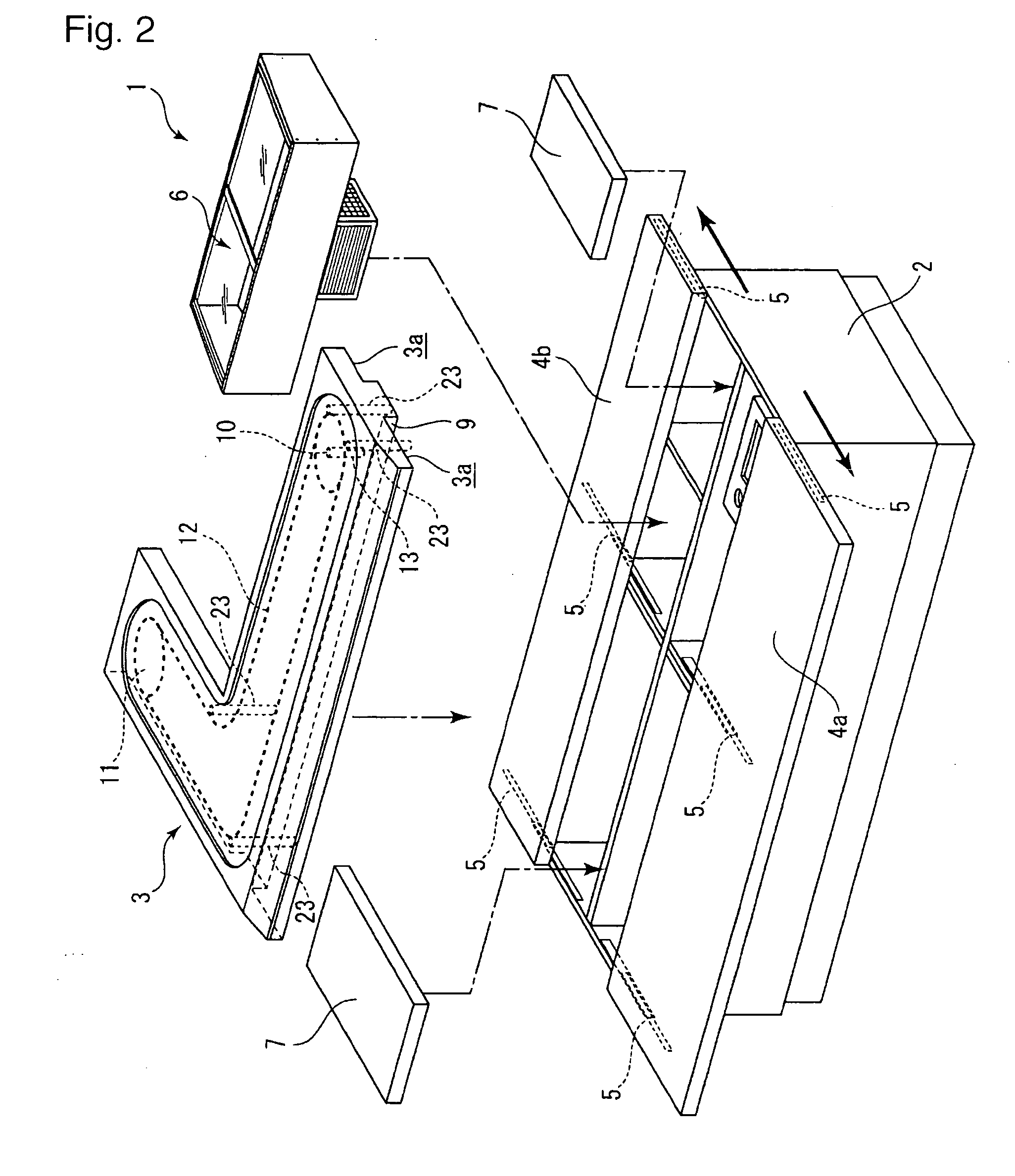
[0051]The embodiments of the present invention are described on the basis of the drawings. First, FIG. 1 is a perspective view illustrating a circulation type conveying device as the embodiment of the present invention. FIG. 2 is an exploded perspective view illustrating the circulation type conveying device in FIG. 1. FIG. 3 is an enlarged view illustrating a fitting condition with a carrying unit. FIGS. 4 (a) and 4 (b) are enlarged cross-section views illustrating the structure of a driving mechanism and the connecting situation of it. And FIG. 5 (a) is a flat surface diagram of the component of the driving mechanism; FIG. 5 (b) is the cross-sectional diagram in line A-A of FIG. 5 (a).

[0052]As FIG. 1 illustrates, the embodiment of the circulation type conveying device of this invention is mainly composed of a box-shaped base 2 having the opening on its upper side, a carrying unit 3 which is placed on top of the base 2 and circulates the transported items such as the sushi plates D...


PUM


Abstract

An object of the present invention is to provide a circulation type conveying device easily transportable, easily assembled in installation, and useful for a user by projecting tables. The circulation type conveying device (1) comprises a base (2), a carrying unit (3) placed on the upper part of the base (2) and cyclically moving carried articles, and the tables (4a) and (4b), wherein the base (2) is opened at least on one part of its upper side, the tables (4a) and (4b) are movable between a position where the opening of the base (2) is closed and a position where they are projected outwardly from the base (2) to open the opening, the carrying unit (3) is able to be placed on the opening portion of the base (2), and the tables (4a) and (4b) and the carrying unit (3) are immovably assembled into the base (2) when the carrying unit (3) is placed on the base (2).

Description

TECHNICAL FIELD[0001]The present invention relates to a circulation type conveying device consisting of a base, a carrying unit which is placed on the upper part of the base and moves cyclically carried articles, and tables.BACKGROUND OF THE INVENTION[0002]Conventionally, circulation type conveying devices with a carrying unit on the upper part of a base and with tables are used as in sushi restaurants called “sushi-go-round restaurant” and food and drink parlors. Such devices move cyclically foods and drinks and so customers can pick their favorite foods and drinks up without their moving. Also they can have some foods and drinks on the tables protruding from the base. For the restaurants, since their employees don't need to serve every customer, the manpower cost and so are able to be decreased as much as possible. (See Patent Document 1)[0003]Nevertheless, regardless how small this circulation type conveying device might be, it is an all-in-one base and tables and carrying unit, ...

Claims


Application Information

Patent Timeline
IPC IPC(8): A47G23/08B65G21/20
CPCA47F10/06
Inventor ISHINO, HARUKIISHINO, SHIGEKIODA, HATSUYOSHISASAHARA, SHINTARO
Owner ISHINO SEISAKUSHOKK
Learn More