
Ultrasonic imaging apparatus

a technology of ultrasonic imaging and imaging apparatus, which is applied in the field of ultrasonic imaging apparatus, can solve the problem that the maximum intensity projection image cannot provide visual comparison between

Inactive Publication Date: 2009-04-16
GE MEDICAL SYST GLOBAL TECH CO LLC
View PDF12 Cites 12 Cited by
  • Summary
  • Abstract
  • Description
  • Claims
  • Application Information

AI Technical Summary

Benefits of technology

[0027]In the invention of the twelfth aspect, overlaid image formation device changes an overlay ratio between first and second images to easy to see them.
[0036]According to the invention, an operator is able to easily make a contradistinction between a second image and a first image overlaid thereon through an overlaid image of the first and second images subjected to maximum intensity projection, make it easy to understand a time change in contrast agent and easily make a contradistinction to all permeation processes of the contrast agent, which occur during the time subsequent to the time required to acquire the second image.

Problems solved by technology

According to the above background art, however, the maximum intensity projection image could not provide visual comparisons between a time change in the distribution of the contrast agent and all permeation processes including the process that the contrast agent will permeate after the acquisition of the maximum intensity projection image.

Method used


Image

  • Ultrasonic imaging apparatus
  • Ultrasonic imaging apparatus
  • Ultrasonic imaging apparatus

Examples


Embodiment Construction

[0048]Various embodiments of an ultrasonic imaging apparatus according to the invention will be explained below with reference to the accompanying drawings. Incidentally, the invention is not limited thereby.

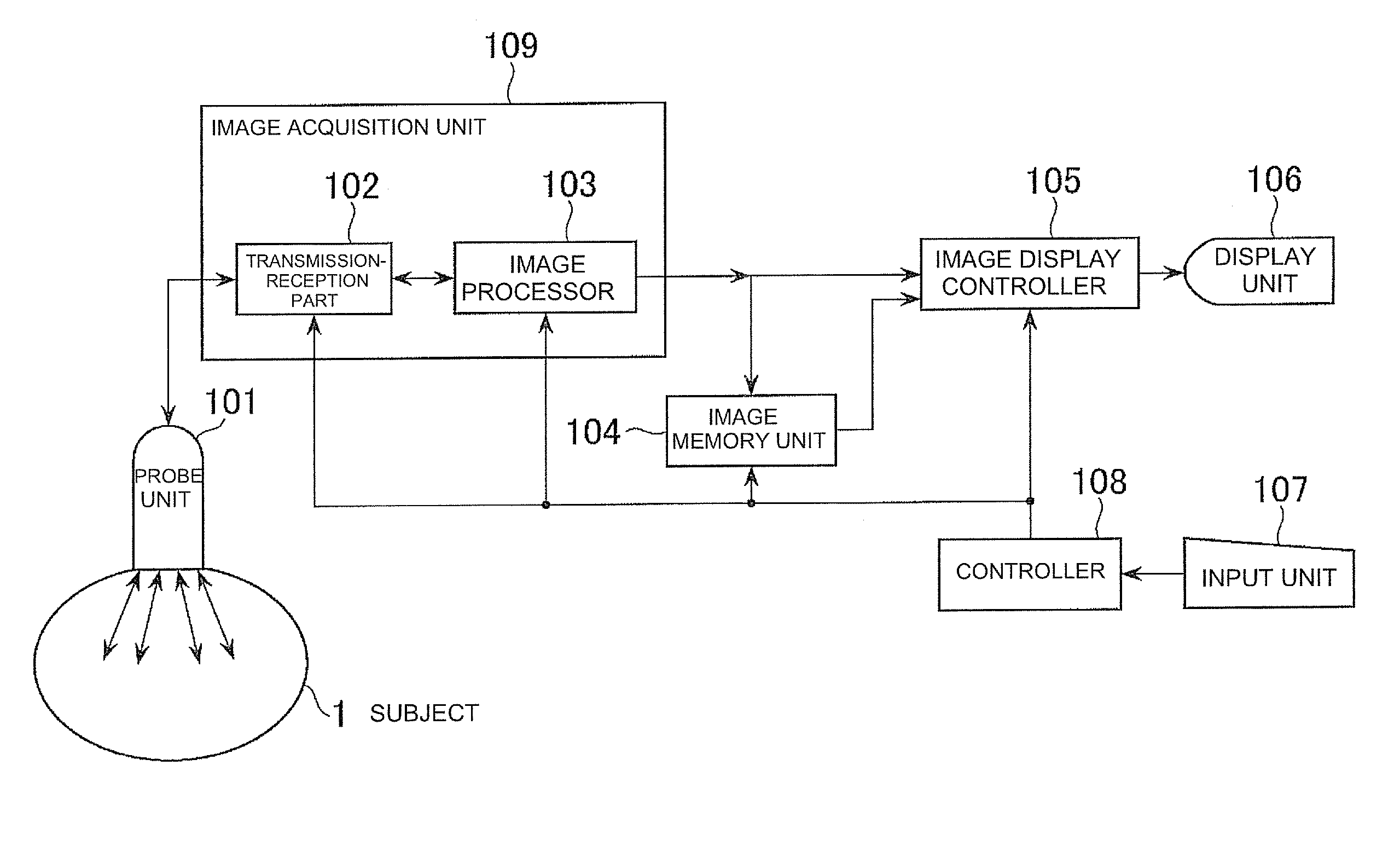
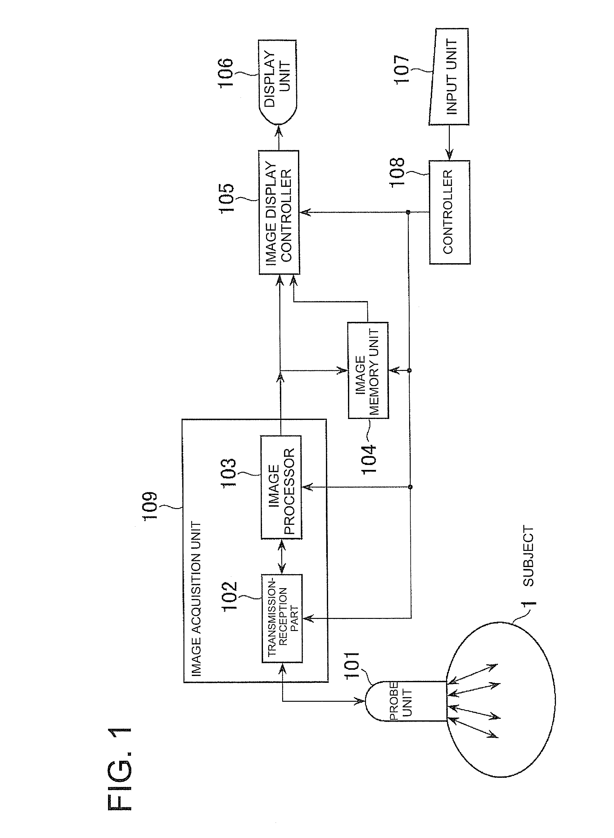
[0049]An overall construction of an ultrasonic imaging apparatus according to a first embodiment will first be explained. FIG. 1 is a block diagram showing the overall construction of the ultrasonic imaging apparatus according to the embodiment 1. The ultrasonic imaging apparatus includes a probe unit 101, an image acquisition unit 109, an image memory unit 104 that constitutes image storing device, an image display controller 105, a display unit 106 that constitutes display device, an input unit 107 and a controller 108.

[0050]The probe unit 101 repeatedly transmits ultrasound in a specific direction of an imaged section of a region, i.e., a subject 1 for transmitting and receiving the ultrasound and receives ultrasonic signals reflected from inside the subject 1 as time-series ...


PUM


Abstract

An ultrasonic imaging apparatus includes an image acquisition device for administering a contrast agent and acquiring B-mode image information, an image storing device for storing the B-mode image information during a predetermined imaging time range from after the administration, a first maximum intensity projection device for forming first maximum intensity projection image information using the B-mode image information acquired in a first time range contained in the imaging time range, a second maximum intensity projection device for forming second maximum intensity projection image information using the B-mode image information acquired in a second time range contained in the first time range, a second image formation device for forming a second image based on the second maximum intensity projection image information, an overlaid image generation device for generating an overlaid image in which the second image is overlaid on a first image of the first maximum intensity projection image information.

Description

CROSS REFERENCE TO RELATED APPLICATIONS[0001]This application claims the benefit of Japanese Patent Application No. 2007-267446 filed Oct. 15, 2007, which is hereby incorporated by reference in its entirety.BACKGROUND OF THE INVENTION[0002]The subject matter disclosed herein relates to an ultrasonic imaging apparatus which images a contrast agent administered to a subject and observes a time change in the contrast agent that permeates through an imaging area thereof.[0003]It has recently been practised to administer a contrast agent to a subject and observe B-mode image in an imaging area, about the blood vessels or a tissue portion or the like through which the contrast agent has permeated, using an ultrasonic imaging apparatus. The B-mode image indicates the manner in which a distribution of the contrast agent in the imaging area changes with time. Upon this imaging, maximum intensity projection (abbreviated as “MIP”) using acquired B-mode images is conducted to make it easier for...

Claims


Application Information

Patent Timeline
Patent Type & Authority Applications(United States)
IPC IPC(8): A61B8/14
CPCA61B8/463A61B8/481G01S7/52084G01S7/52074G01S7/52071
Inventor HASHIMOTO, HIROSHI
Owner GE MEDICAL SYST GLOBAL TECH CO LLC
Learn More