
Disk scheduling method and apparatus

Inactive Publication Date: 2009-04-16
ELECTRONICS & TELECOMM RES INST
View PDF18 Cites 31 Cited by
  • Summary
  • Abstract
  • Description
  • Claims
  • Application Information

AI Technical Summary

Benefits of technology

[0017]Accordingly, it is an object of the present invention to provide a method and apparatus capable of efficiently scheduling requests whose deadlines are close to each other.
[0018]It is another object of the present invention to provide a disk scheduling method and apparatus for processing requests in priority order whose deadlines are close to each other, thereby efficiently meeting both the deadlines and priorities.
[0019]It is still another object of the present invention to provide a disk scheduling method and apparatus for processing requests in priority order whose deadlines are close to each other, thereby preventing processing of any requests having relatively higher priorities from being delayed due to a process based on deadline order.

Problems solved by technology

Therefore, resource starvation may occur in a request for a specific sector of a track that is far from the current position of the disk head in the direction in which the disk head moves across tracks.
However, this may not meet the deadline or priority of a specific request.
Therefore, resource starvation may occur in a specific request.
Therefore, a large amount of overhead may occur in searching for requests whose deadlines are not ensured whenever a new request is inserted.
However, when requests concentrate on a queue having a relatively low service ratio, for example, a queue where a periodic disk requests are arranged, resource starvation may occur in a specific request of the queue.
Other disk scheduling techniques according to the related art do not propose any efficient solutions capable of processing a case when deadlines of requests are close to each other.
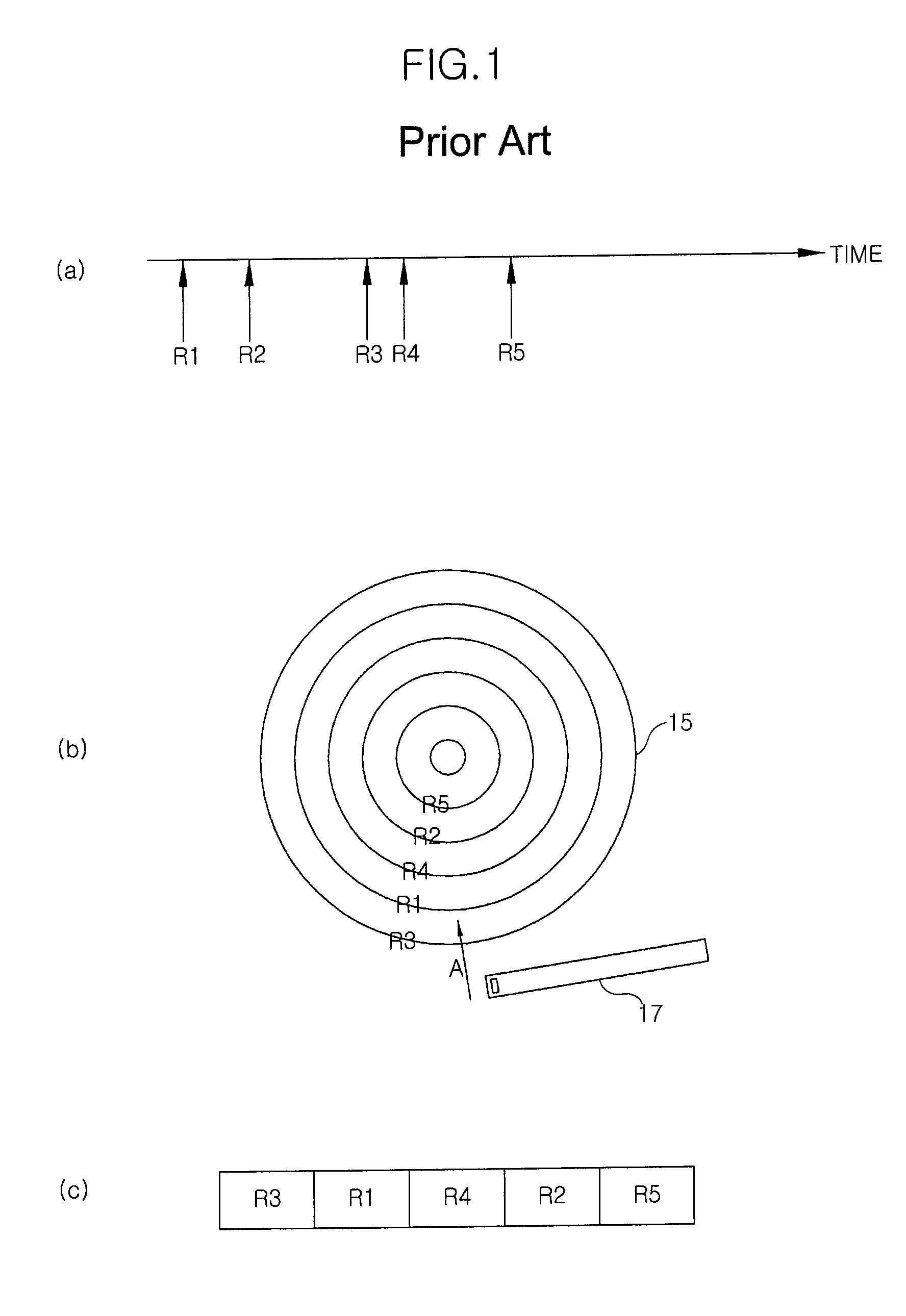
In the disk scheduling techniques according to the related art, when deadlines of requests are close to each other, some of the requests may not be immediately processed, but processing thereof may be delayed even though their deadlines have passed.

Method used


Image

  • Disk scheduling method and apparatus
  • Disk scheduling method and apparatus
  • Disk scheduling method and apparatus

Examples


first embodiment

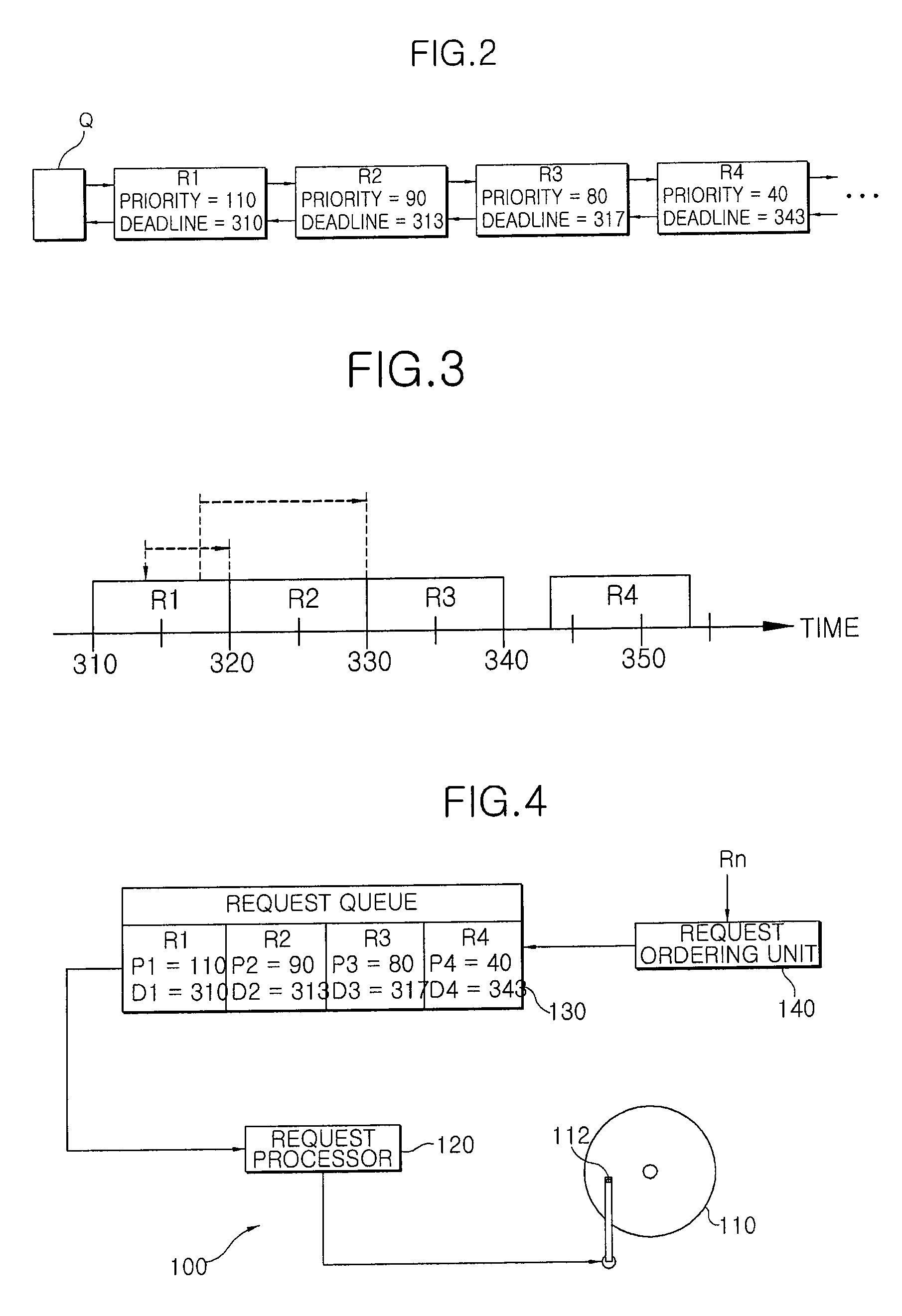
[0040]FIG. 4 shows the configuration of a disk scheduling apparatus 100 according to this embodiment. The disk scheduling apparatus 100 includes a request processor 120 that provides commands required to position a disk head 112 for a reading / writing operation on a disk 110, a request queue 130 where requests are arranged to be processed by the request processor 120, and a request ordering unit 140 that orders input requests and inserts the input requests into the request queue 130. Requests R1 to Rn are associated with information on deadlines D1 to Dn, priorities P1 to Pn, and access positions on the disk 110. The smaller number represents the higher priority.

[0041]In this embodiment, the request ordering unit 140 orders input requests in deadline order and inserts the input requests into the request queue 130. The request processor 120 processes the requests from the lead request R1 of the request queue 130 sequentially. When a new request is input, the request ordering unit 140 ...

second embodiment

[0052]The second embodiment is different from the first embodiment in that requests are processed in the scanning order in a normal state and any requests reaching their deadlines during normal processing are preferentially processed. Meanwhile, this embodiment is similar to the first embodiment in that requests whose process times based on deadline order overlap each other are reordered and processed in priority order.

[0053]FIG. 9 shows a disk scheduling apparatus 200 according to this embodiment. Hereinafter, only the different portions of this embodiment from the first embodiment will be described and a description of portions similar to or same as the first embodiment will be omitted. A request ordering unit 240 orders requests R1 to R4 of a request queue 230 in the scanning order in a direction B in which a disk head 212 moves across tracks. Further, the request ordering unit 240 searches the request queue 230 to determine whether a request or request group reaching or having m...

third embodiment

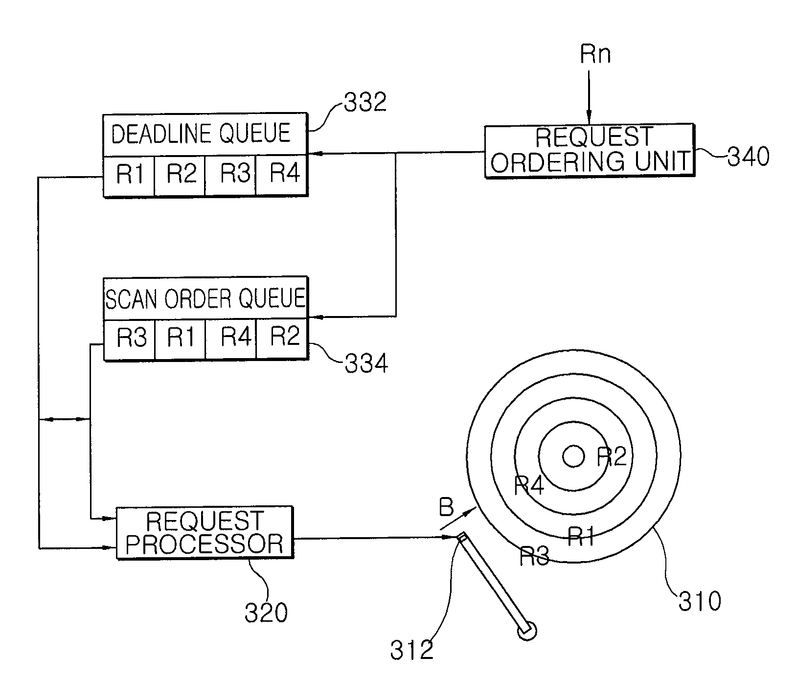
[0056]The third embodiment has a characteristic that it uses a deadline queue 332 and a scan order queue 334, instead of the request queue 230. The other functions are the same as those in the second embodiment.

[0057]Referring to FIG. 10, input requests are simultaneously inserted into both the deadline queue 332 and the scan order queue 334. Then, a request ordering unit 340 orders the requests inserted into the deadline queue 332 in the same manner as that in the first embodiment. That is, the requests inserted into the deadline queue 332 are arranged in deadline order and any requests whose deadlines are close to each other (whose process times overlap each other) are arranged in priority order. Further, the request ordering unit 340 arranges the requests inserted into the scan order queue 334 in the scanning order.

[0058]A request processor 320 processes the requests from the scan order queue 334 unless any requests reaching their deadlines or having missed their deadlines exist....


PUM


Abstract

The present invention relates to a method and apparatus for scheduling requests having priorities and deadlines for an I / O operation on a disk storage medium. Requests are normally arranged and processed in deadline order, and requests whose process times based on deadlines overlap each other are processed in priority order. Therefore, it is possible to prevent processing of any requests having relatively higher priorities from being delayed due to a process based on deadline order. Further, in order to minimize seek time, the requests may also be processed in the scanning order. Furthermore, in order to minimize a time required for performing request search and arrangement in the scanning order and the deadline order, a deadline queue where requests are arranged in deadline order and a scan order queue where requests are arranged in the scanning order may be separately prepared.

Description

BACKGROUND OF THE INVENTION[0001]1. Field of the Invention[0002]The present invention relates to a technique of processing data requests for a storage medium, and more particularly, to a method and apparatus for scheduling requests for input and output operations on a disk storage medium.[0003]The invention was supported by the IT R&D program of MIC / IITA. [2006-S038-02, Development of Device-Adaptive Embedded Operating System for Mobile Convergence Computing][0004]2. Description of the Related Art[0005]Disk scheduling algorithms may be implemented, for example, in general-purpose operating system software or drive firmware. A disk scheduling algorithm may reorder data requests to a storage medium, for example, a hard disk, a floppy disk, and a CD, scheduled to be accessed by a computer, to minimize seek time of a disk head, thereby maximizing a data processing rate. Data requests are, for example, input / output (hereinafter, simply referred to as I / O) requests for writing data on a d...

Claims


Application Information

Patent Timeline
IPC IPC(8): G06F9/46G06F3/06
CPCG06F3/061G06F2209/5021G06F3/0676G06F3/0659G06F13/00G06F13/18G06F12/00G06F12/08
Inventor KANG, DONGWOOKKIM, JAEMYOUNG
Owner ELECTRONICS & TELECOMM RES INST
Learn More