Method for Contention-Based Scheduling of Downlink Signal Transmissions

Active Publication Date: 2013-11-14
LG ELECTRONICS INC +1
View PDF1 Cites 7 Cited by
  • Summary
  • Abstract
  • Description
  • Claims
  • Application Information

AI Technical Summary

Benefits of technology

[0042]According to embodiments of the present invention, downlink signal transmission can be efficiently scheduled in a contention-based manner.
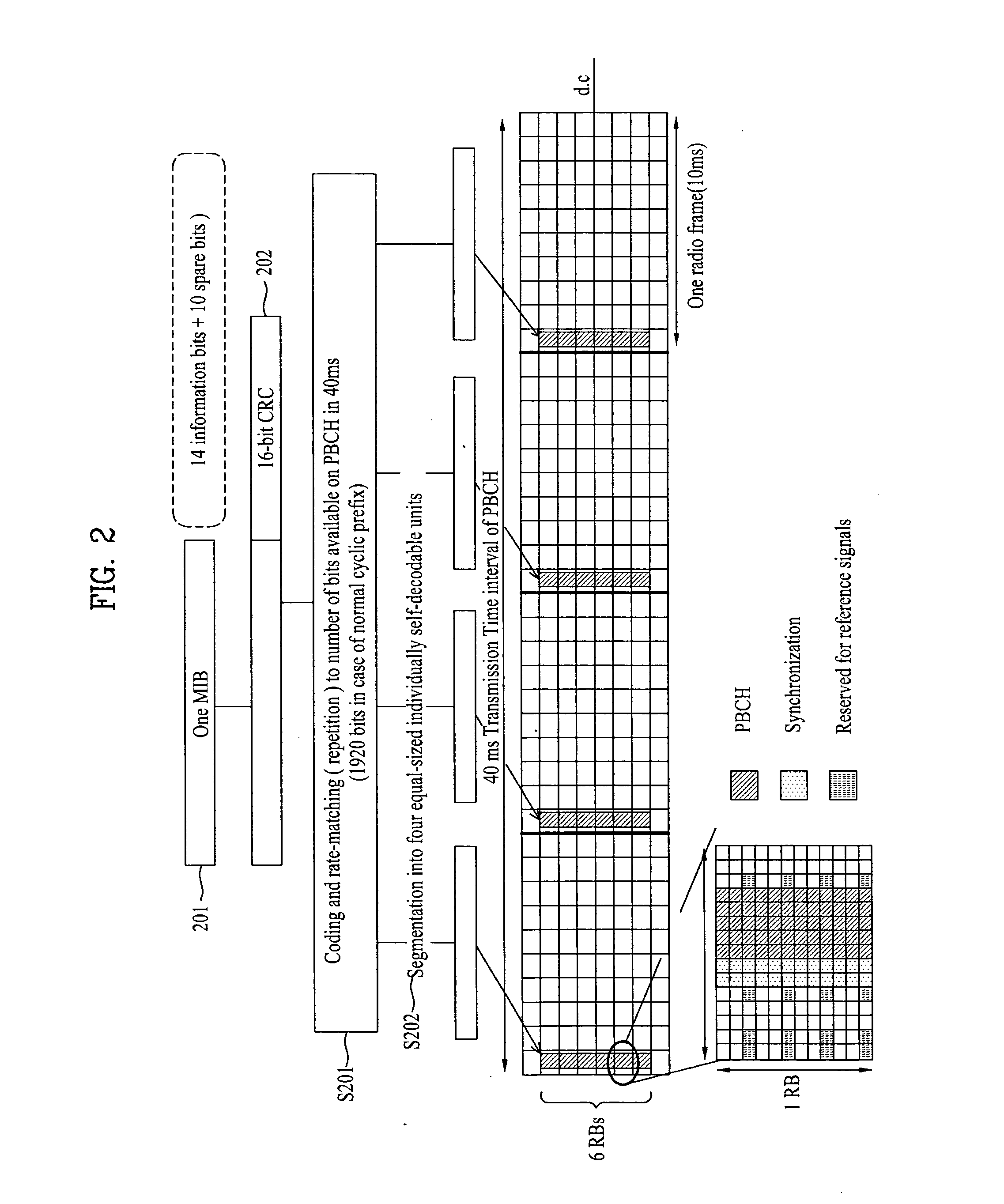
[0043]Especially in a 3GPP LTE system, a UE and a BS for performing contention-based scheduling of downlink signal transmission without defining an additional channel and a method for efficiently operating the UE and the BS are provided. Specifically, each BS transmits contention information on a Physical Broadcast Channel (PBCH) defined in the 3GPP LTE system and a UE broadcasts a contention number with a highest priority level. Hence, signaling overhead is decreased, compared to a method for indicating whether each BS has won a contention.
[0044]In the case where each UE transmits contention information (a maximum contention number among contention numbers of adjacent neighbors and the presence or absence of a BS that does not support contention mode or a BS that is not operating in the contention mode) K times repeatedly, each BS can more reliably extract contention numbers broadcast by UEs supporting the contention mode even though UEs adjacent to the BS, which do not support the contention mode, transmit uplink signals.
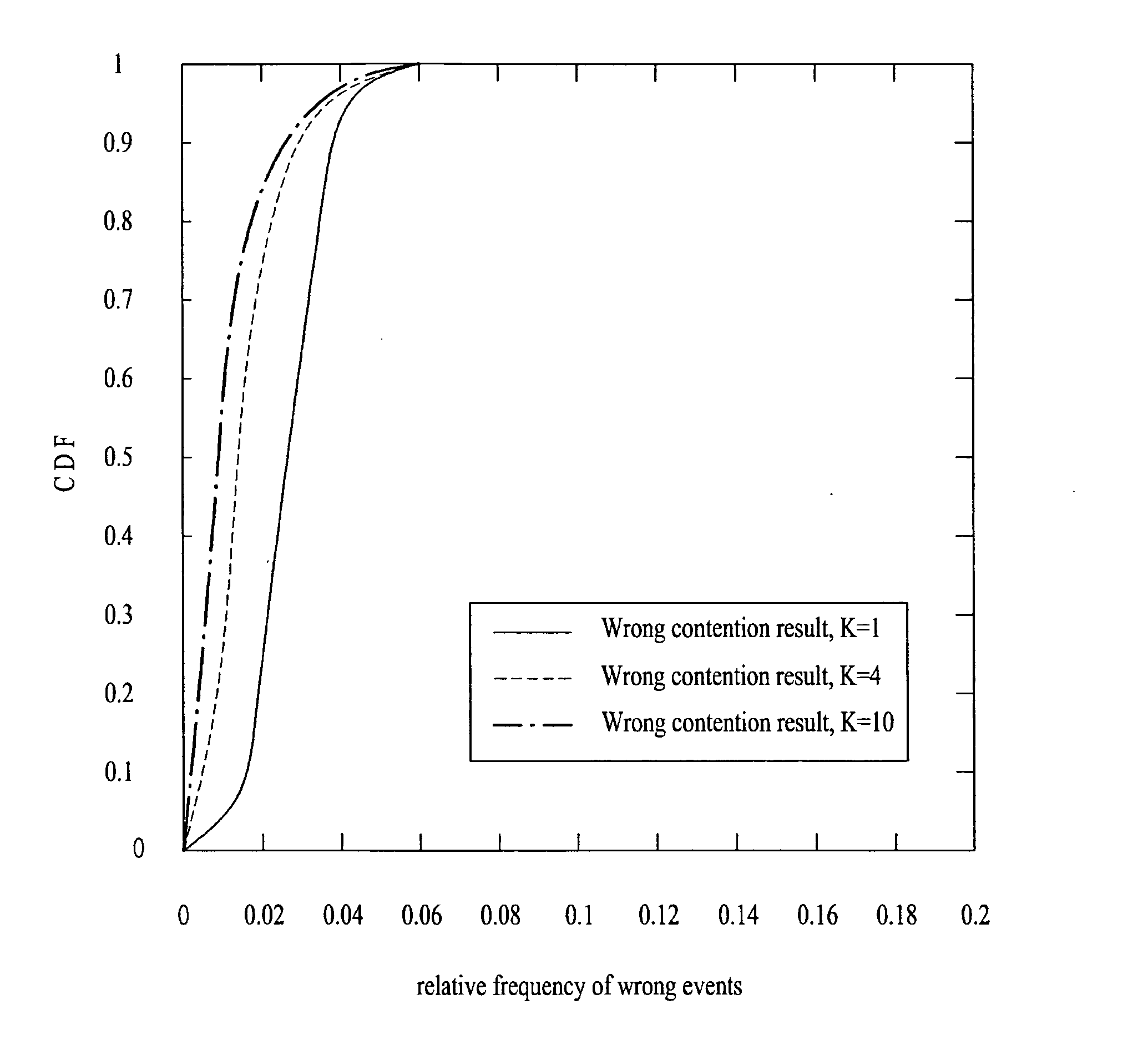
[0045]A contention-mode BS may wrongly determine that it is a winner or a loser when it is a loser or a winner in fact. This is referred to as a wrong contention result. If the BS has won

Problems solved by technology

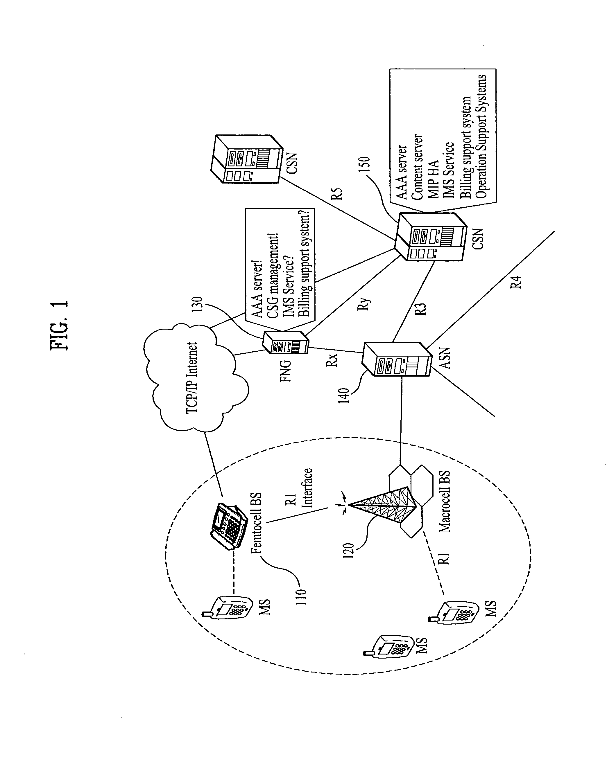
However, femtocell BSs are purchased and installed by users and thus the deployment positions of the femtocell BSs are not only difficult to estimate and but also variable.
Moreover, along with the proliferation of femtocell BSs, the femtocell BSs are distributed densely and thus it is expected that interference between femtocell BSs is more severe than interference between legacy BSs (operated by mobile communication service providers).
Unlike the legacy BSs, there is no direct link between femtocell BSs, which makes it difficult to solve the interference problem by conventional power-based or code-based interferenc

Method used


Image

  • Method for Contention-Based Scheduling of Downlink Signal Transmissions
  • Method for Contention-Based Scheduling of Downlink Signal Transmissions
  • Method for Contention-Based Scheduling of Downlink Signal Transmissions

Examples


Example

BEST MODE

[0067]Reference will now be made in detail to the preferred embodiments of the present invention with reference to the accompanying drawings. The detailed description, which will be given below with reference to the accompanying drawings, is intended to explain exemplary embodiments of the present invention, rather than to show the only embodiments that can be implemented according to the invention. The following detailed description includes specific details in order to provide a thorough understanding of the present invention. However, it will be apparent to those skilled in the art that the present invention may be practiced without such specific details. For example, the following detailed description is given under the assumption that a 3rd Generation Partnership Project (3GPP) Long Term Evolution (LTE) system is being used. However, the description is applicable to any other mobile communication system except for specific features inherent to the 3GPP LTE system.

[0068...


PUM


Abstract

A method and apparatus for operating a UE and a BS to perform contention-based scheduling of downlink signal transmissions are disclosed. The method includes receiving, from at least one of BSs adjacent to the UE, a channel carrying inter-BS contention information for downlink signal transmission in an (n+1)th time unit, n being an integer, broadcasting to the BSs a contention number with a highest priority level among contention numbers extracted from the inter-BS contention information, and receiving a downlink signal from a BS that transmitted inter-BS contention information related to the contention number with the highest priority level in the (n+1)th time unit.

Description

TECHNICAL FIELD[0001]The present invention relates to a method and apparatus for operating a User Equipment (UE) and a Base Station (BS) to schedule downlink signal transmissions in a contention-based manner.BACKGROUND ART[0002]In a wireless communication system, BSs use frequency, power or code resources to reduce mutual interference.[0003]In a frequency-based inter-BS interference control scheme, different frequencies are allocated to adjacent BSs so that interference does not physically reach the BSs. A power-based inter-BS interference control scheme regulates that power equal to or higher than a predetermined level is not used in order to avoid severe interference between BSs or UEs. Interference can be reduced by allocating different quasi-orthogonal codes to BSs so that the BSs transmit signals by multiplying them by their allocated unique codes. This is a code-based inter-BS interference control scheme. When inter-BS interference is controlled using frequency, perfectly diff...

Claims


Application Information

Patent Timeline
IPC IPC(8): H04W72/04
CPCH04W72/0426H04L1/1867H04L5/0048H04L5/0053H04L5/0064H04L5/0091H04W72/27H04W72/56
Inventor JO, JUN HOBAHK, SAE WOONGPARK, SANG KYUKIM, KI JUNYOON, SUNG GUK
Owner LG ELECTRONICS INC
Why Eureka
Try Eureka