Electrical-Energy Generator

a generator and electric energy technology, applied in the direction of motors, electrical apparatus, dynamo-electric machines, etc., can solve the problem of significant establishment cost slowing down

Inactive Publication Date: 2009-04-23
M ARIZA GARCIA SAN MIGUEL JOSE +1
View PDF7 Cites 23 Cited by
  • Summary
  • Abstract
  • Description
  • Claims
  • Application Information

AI Technical Summary

Problems solved by technology

For the proper performance of the aerogenerators, a large air flow is required, thus involving in addition to the large investment expenses in the relevant apparatus, the requirement of setting them up in specific areas, usually in extremely high mountain regions with virtually constant wind in order to render them profitable, hence implying significant establishment costs slowing-down to a great extent the practical implementation.

Method used


Image

  • Electrical-Energy Generator
  • Electrical-Energy Generator
  • Electrical-Energy Generator

Examples


Embodiment Construction

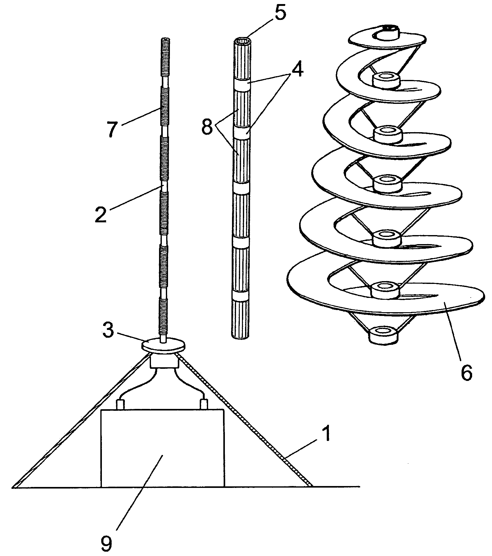
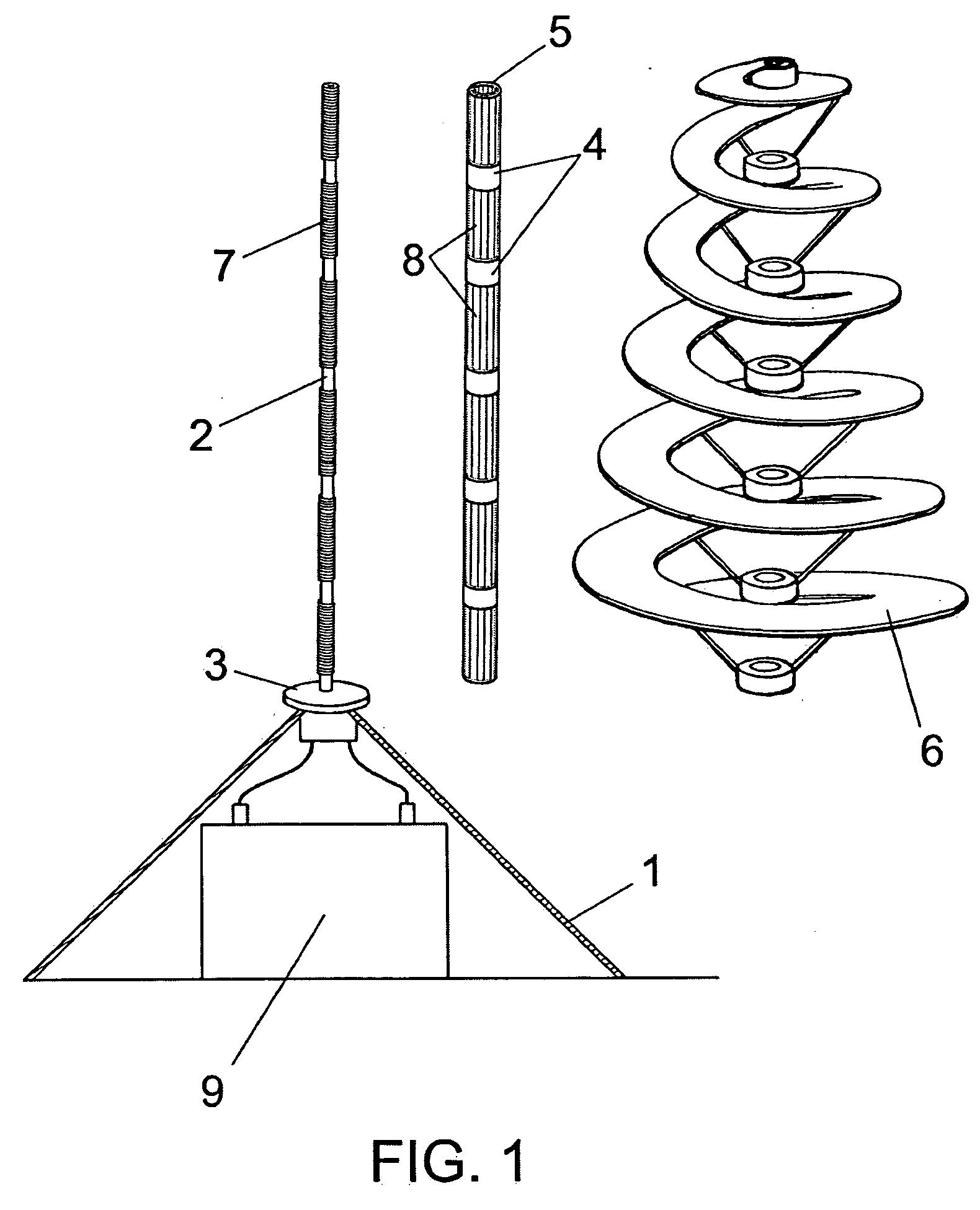
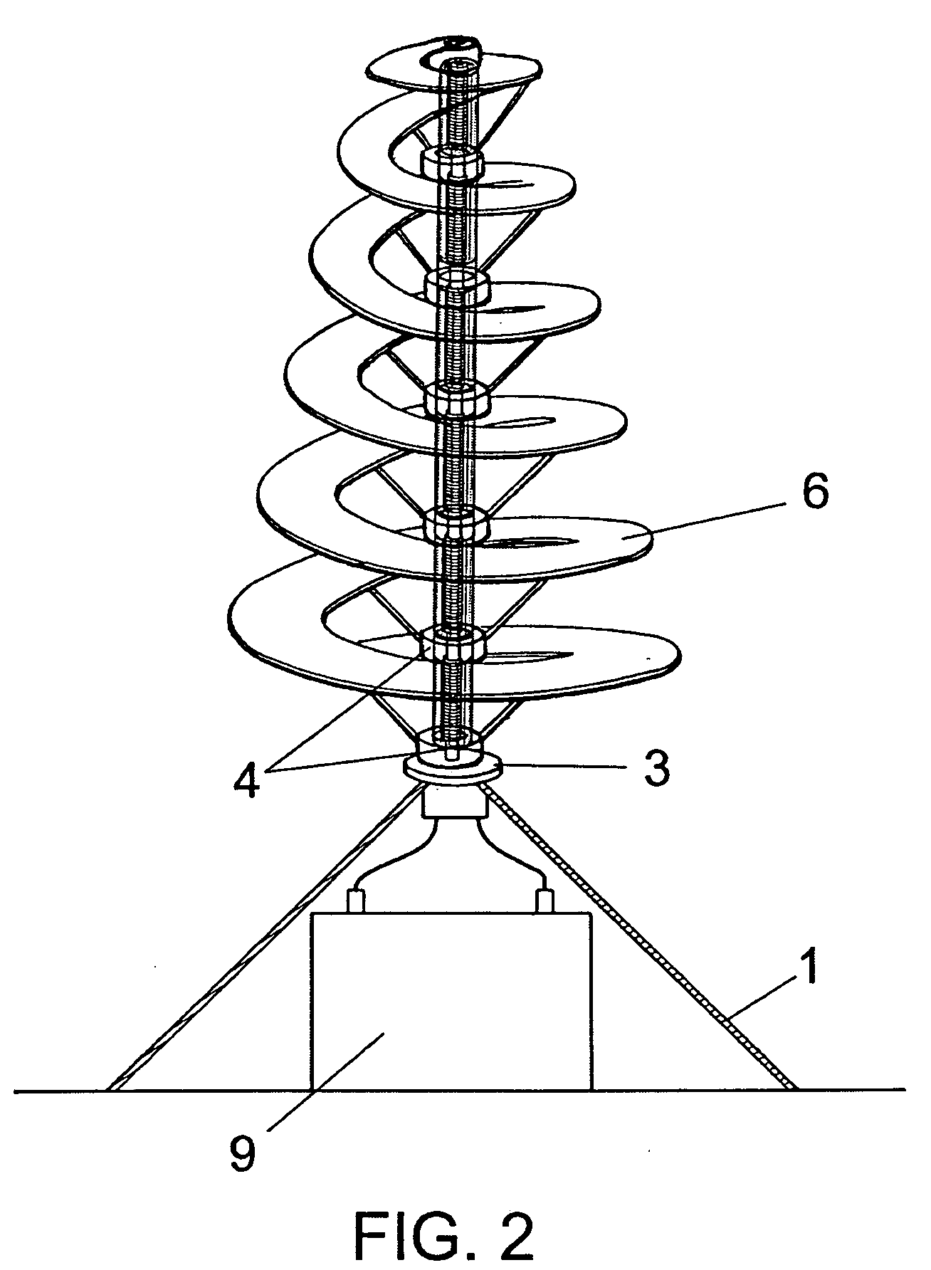
[0013]Upon viewing the mentioned figures, it can be observed that the power generator proposed in the present invention comprises a supporting plinth or base (1), that can be built into the ground or appropriately supported by it or by any suitable support; a fixed axis emerges vertically from the plinth (2), whose height is adequate and on which, by means of a lower axial bearing (3), a number of radial bearings are assembled (4) and a second tubular axis (5), that in turn supports a conic-helicoid-shaped blade (6).

[0014]The axis (2), also being tubular, is equipped with an electric coil (7) in its interior, thus acting as a stator, while a number of permanent magnets (8) are placed on the outer tubular axis (5), whereby the axis works as a rotor, appropriately propelled by the blade (6).

[0015]The rotary movement of the permanent magnets (8) supplied to the generator by the blade (6) due to the effect of the wind, generates a variable magnetic field in which the coil (7) of the sta...


PUM


Abstract

Electrical-energy generator of the type that incorporate a plinth or pedestal from which emerges a vertical, fixed shaft on which is mounted, via bearings, a second shaft to which a blade of conical, helicoidal shape is secured, which imparts a rotary movement to the movable shaft through the effect of the wind, characterized in that said fixed shaft is tubular and incorporates within it an electrical winding functioning as stator, whilst the movable shaft, which is also tubular, incorporates within it a plurality of permanent magnets that convert it into a rotor, all the aforesaid in such a manner that the actual shaft of the generator simultaneously constitutes the dynamo or the alternator that converts the mechanical energy into electrical energy.

Description

[0001]The present invention refers to an electric power generator, of the type that converts wind power into electric power.[0002]The purpose of the invention is thus to devise a generator capable of using wind power, in order to convert it into electric power, having a straightforward, economical and effective structuring specifically affecting power conversion means, using the wind movement sensors as a power conversion means.BACKGROUND OF THE INVENTION[0003]Within the fields pertaining to wind power conversion, the standard method used for converting such energy into electric power involves aerogenerators, that incorporate a mast of considerable diameter and height, on whose upper end is a horizontally mounted rotor supporting a number of blades that are likewise of considerable weight and size, intended to be activated by the wind in a similar way as in a traditional windmill, in order to provide the axis with a rotary movement that can be used by an alternator or electric gener...

Claims


Application Information

Patent Timeline
Patent Type & Authority Applications(United States)
IPC IPC(8): F03D9/02
CPCF03D3/061F03D9/021F05B2220/7068Y02E10/74F05B2250/232F05B2250/25H02K7/183F05B2240/30F03D9/11Y02E70/30F03D80/70F03D9/25
Inventor M' ARIZA GARCIA SAN MIGUEL, JOSECASARES PELAEZ, ENRIQUE
Owner M ARIZA GARCIA SAN MIGUEL JOSE
Why Eureka
Try Eureka