Apparatus and method for tuning a radio frequency antenna

a radio frequency antenna and apparatus technology, applied in the field of apparatus and method for tuning an rf antenna, can solve the problems of document easily being lost or damaged, inability to update the initial barcode itself with new information, and burdensome tasks

Inactive Publication Date: 2009-04-23
ACCU SORT
View PDF3 Cites 36 Cited by
  • Summary
  • Abstract
  • Description
  • Claims
  • Application Information

AI Technical Summary

Problems solved by technology

This could be a burdensome task depending on the number of components required to be installed, the number of installers, and the type of product.
The document could easily be lost or damaged during the transfer from one assembler to the next, and so on.
Due to the limitations of barcodes, however, the initial barcode itself cannot be updated with new information, including an identification of which components have recently been installed in the product, once the barcode has been printed and affixed to the product.
This process is inefficient and can become tedious where it requires attachment of a new barcode to the product or its packaging each time the product is updated.
Installation of multiple barcode printers may also be required if the assemblers' workstations are remotely located from one another, increasing the cost of maintaining the workflow record.
Although barcode scanners placed along the conveyor system could read the barcode label attached to the product or its packaging, the scanners require an uninterrupted line of sight to the barcode.
A direct line of sight from the scanner to the barcode is often infeasible due to the size, shape, placement, or orientation of the product or its packaging.
RFID tags are relatively small and inconspicuous to the purchaser when applied to the product or its packaging.
The resonant frequency of such antenna systems, however, can be susceptible to change created by objects located near the antennas when the systems are installed in the field.

Method used


Image

  • Apparatus and method for tuning a radio frequency antenna
  • Apparatus and method for tuning a radio frequency antenna
  • Apparatus and method for tuning a radio frequency antenna

Examples


Embodiment Construction

[0036]Reference will now be made in detail to presently preferred embodiments of the invention, one or more examples of which are illustrated in the accompanying drawings. Each example is provided by way of explanation of the invention, not limitation of the invention. In fact, it will be apparent to those skilled in the art that modifications and variations can be made in the present invention without departing from the scope or spirit thereof. For instance, features illustrated or described as part of one embodiment may be used on another embodiment to yield a still further embodiment. Thus, it is intended that the present invention covers such modifications and variations as come within the scope of the appended claims and their equivalents.

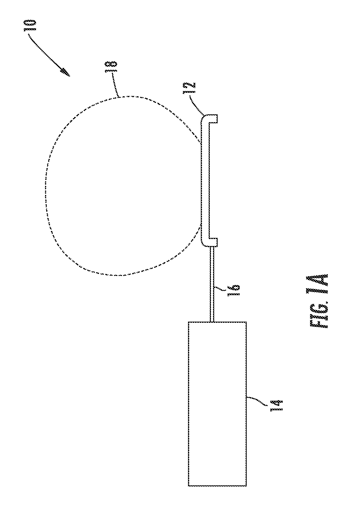
[0037]FIG. 1A illustrates a conventional antenna system 10 comprising an antenna 12 connected to a reader 14 via a feed line 16. In operation, reader 14 provides antenna 12 with a modulated radio frequency signal via feed line 16, referred to ...


PUM


Abstract

The present invention provides a radio frequency identification tag reader system, that comprises a radio frequency identification tag reader that outputs a drive signal at a predetermined frequency at which a radio frequency tag operates, an antenna that receives the drive signal and radiates an electromagnetic field in response to the drive signal, a tuning circuit disposed between the reader and the antenna so that the drive signal passes through the tuning circuit, wherein the tuning circuit has at least one component that defines a selectable, variable electrical characteristic that selects a resonant frequency of the antenna, a sensor circuit in communication with the antenna so that the sensor circuit detects a response by the antenna to the drive signal and outputs a sensor signal that corresponds to power of an electromagnetic field radiated by the antenna in response to the drive signal, and a processor in communication with the tuning circuit so that the processor controls the selectable component, and wherein the processor receives the sensor signal and sets the variable electrical characteristic in response to the sensor signal.

Description

FIELD OF THE INVENTION[0001]The present invention relates generally to radio frequency (“RF”) antennas, and more particularly, to an apparatus and method for tuning an RF antenna.BACKGROUND OF THE INVENTION[0002]Numerous products, such as computers and other electronic devices, contain a number of smaller components that must be connected together and configured in order for the final product to be complete. In the example of computer assembly, generally at least a processor, memory, and a storage device must be attached to a motherboard for the computer to operate. Other components, such as peripherals and software, are required for the computer to properly function. Products including multiple components such as these may be handled by various people during the assembly process.[0003]Manufacturers of such products generally require that a record documenting the workflow process of a product's assembly be maintained by the assemblers. The assemblers use the record to document all a...

Claims


Application Information

Patent Timeline
Patent Type & Authority Applications(United States)
IPC IPC(8): G08B13/14
CPCG06K7/0008H01Q1/2216H03J2200/10H03J5/244H01Q7/00
Inventor HILLEGASS, RAYMOND R.
Owner ACCU SORT
Why Eureka
Try Eureka