Ink supply assembly for an ink jet printing device

a technology assembly, which is applied in the direction of printing, ink apparatus, etc., can solve the problems of pressure fluctuations, acceleration and deceleration of printheads, and mass or inertia of liquid inks, and achieves the effect of improving the image quality of ink jet printing devices and simple construction

Active Publication Date: 2009-04-23
OCE TECH
View PDF7 Cites 11 Cited by
  • Summary
  • Abstract
  • Description
  • Claims
  • Application Information

AI Technical Summary

Benefits of technology

[0007]It is an object of the present invention to provide an ink supply assembly that has a compact and simple construction and permits an improved image quality of the ink jet printing device.

Problems solved by technology

For example, such pressure fluctuations may be induced, especially in a page wide printer, when a large demand for ink occurs in a certain region of the printhead because almost all nozzles in that region are firing.
When the demand for ink ceases abruptly, this will create a pressure surge that may influence the drop forming characteristics and hence the print quality.
Moreover, when the printhead is moved relative to the frame of the printer, the accelerations and decelerations of the printhead and the mass or inertia of the liquid ink may also give rise to pressure fluctuations.

Method used


Image

  • Ink supply assembly for an ink jet printing device
  • Ink supply assembly for an ink jet printing device
  • Ink supply assembly for an ink jet printing device

Examples


second embodiment

[0071]FIGS. 14 to 17 illustrate an ink distribution tile according to the present invention. This tile is formed by a sandwich structure of plate members 66, 68 and polyimide foils (not shown) interposed therebetween and is disposed on the top and bottom of the structure. FIG. 14 is a top view of the top plate member 66, FIG. 15 is a bottom view thereof, FIG. 16 is top view of the second plate member 68, and FIG. 17 is a bottom view of the second plate member. In all these Figures, recessed portions are indicated as hatched areas.

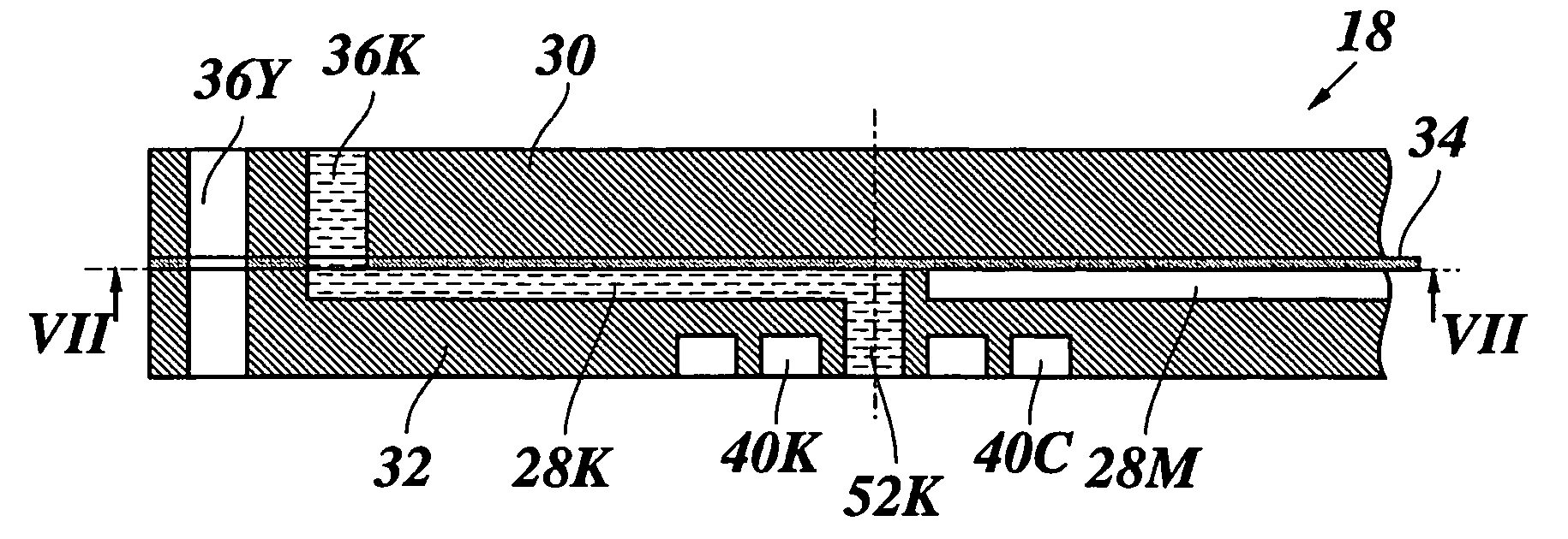
[0072]As is shown in FIG. 14, the first plate member 66 has four through-holes serving as inlet ports 36Y and 36C for yellow and cyan ink. The foil (not shown) covering the top surface of this plate member 66 is formed with eight elongate through-holes of which four are aligned with the inlet ports 36Y, 36C and the other four are arranged in similar pattern as in FIG. 7 and directly serve as inlet ports for black and magenta inks. Through these inlet ports,...

first embodiment

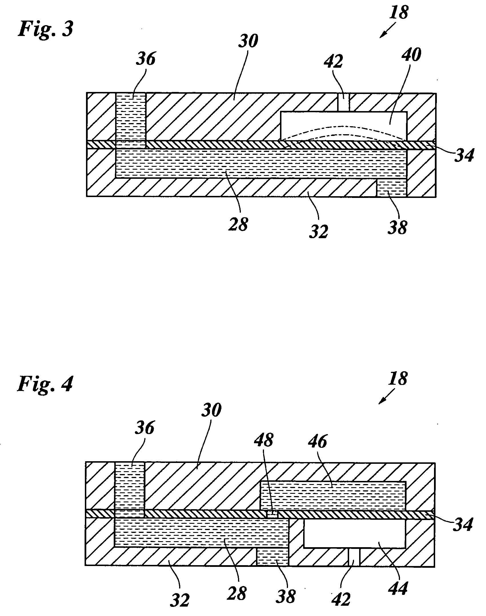
[0077]Black ink that has entered into the ink passage 28K will enter into the connection chamber 70K and from there, via the flow-restricting through-hole 48, into the ink chamber 46K formed in the top surface of the plate member 68. This ink chamber 46K is congruent with and opposed to the air chamber 44K on the bottom side of the plate member 66 (FIG. 15), and the ink chamber and the air chamber are separated by the flexible foil interposed between the two plate members. Thus, pressure fluctuations in the black ink can be attenuated similarly as in the

[0078]The same holds true for the magenta ink introduced into the ink passage 28M.

[0079]The ink in yellow and cyan that has entered through the inlet ports 36Y and 36C (FIG. 14) will be introduced into ink passages 28Y and 28C formed in the bottom surface of the second plate member 68 (FIG. 17), from where they will enter into slot-like outlet ports 38Y and 38C. The foil (not shown) covering the bottom surface of the plate member 68 ...


PUM


Abstract

An ink supply assembly includes at least one inlet port. At least one outlet port is connected to the inlet port via an ink cavity and is adapted to be connected to an ink discharge unit of an ink jet device. The ink supply assembly has a sandwich structure formed by at least two plate members and a foil that is interposed therebetween and has a part forming a wall of said ink cavity. At least one of the plate members defines a pressure equalization chamber adjacent to the ink cavity and separated therefrom by the foil.

Description

CROSS-REFERENCE TO RELATED APPLICATIONS[0001]This application claims priority under 35 U.S.C. §119(a) to Application No. 07119087.0, filed in Europe on Oct. 23, 2007, the entirety of which is expressly incorporated herein by reference.BACKGROUND OF THE INVENTION[0002]1. Field of the Invention[0003]The present invention relates to an ink supply assembly including at least one inlet port, at least one outlet port connected to the inlet port via an ink cavity and adapted to be connected to an ink discharge unit of an ink jet device. The assembly has a sandwich structure formed by at least two plate members and a foil that is interposed therebetween and has a part forming a wall of the ink cavity. At least one of said plate members defines a pressure equalization chamber adjacent to the ink cavity and separated therefrom by said foil.[0004]2. Description of Background Art[0005]A known ink supply assembly of this type has been described in EP-A-1 658 978. Another known ink supply assembl...

Claims


Application Information

Patent Timeline
Patent Type & Authority Applications(United States)
IPC IPC(8): B41J2/175
CPCB41J2/055B41J2/155B41J2202/20B41J2002/14491B41J2002/14419
Inventor RUTTEN, HENDRIK G.REINTEN, HANS
Owner OCE TECH
Why Eureka
Try Eureka