Optic positioning device

a positioning device and optical technology, applied in the field of lighting apparatuses, can solve problems such as breaking the legs or other elements involved in mounting, and achieve the effect of insertion and removal of optics

Active Publication Date: 2009-04-23
LSI INDS
View PDF27 Cites 48 Cited by
  • Summary
  • Abstract
  • Description
  • Claims
  • Application Information

AI Technical Summary

Benefits of technology

[0009]In yet another aspect of the invention, the light-exiting end of each optic is retained by a slot opening formed into each sidewall, adjacent the aperture of the base. If the optic is annular and frustum-shaped, the slot opening has an upper edge that engages the upper rim of the optic lens, which is typically a linear segment, and a curved lower edge that intersects the upper edge and provides clearance for, and typical engagement with, a portion of the conical sidewall of the optic. Alternatively, each slot opening can be rectangular, triangular, or other shape, and the upper edge need not be linear, but can be curved or irregular in shape. When the frustum-shaped optic lens is manipulated into and within the channel at the optic holding position, with its light-entering end extending through the aperture of the base, a portion of the upper rim of the optic extends at least partially through each slot opening, whereby the upper edges of the slot opening retains the optic from movement in the +Z direction. Typically, each sidewall portion is rigidly fixed to, and optionally integrally with, the base portion of the channel. The material of the device is preferably sufficiently flexible to allow the sidewalls to flex outwardly, away from the other sidewall, sufficiently to allow the opposed rim portions of the optic to pass beyond the distal edges of the sidewalls and into or through the slot openings facilitating insertion and removal of the optic.

Problems solved by technology

An optical lens is commonly affixed to the LED device or to the PCB one lens at a time, and in an irreversible manner, in that removal of an lens (if, for example, improperly installed) usually results in breaking the legs or other element involved in mounting.

Method used


Image

  • Optic positioning device
  • Optic positioning device
  • Optic positioning device

Examples


first embodiment

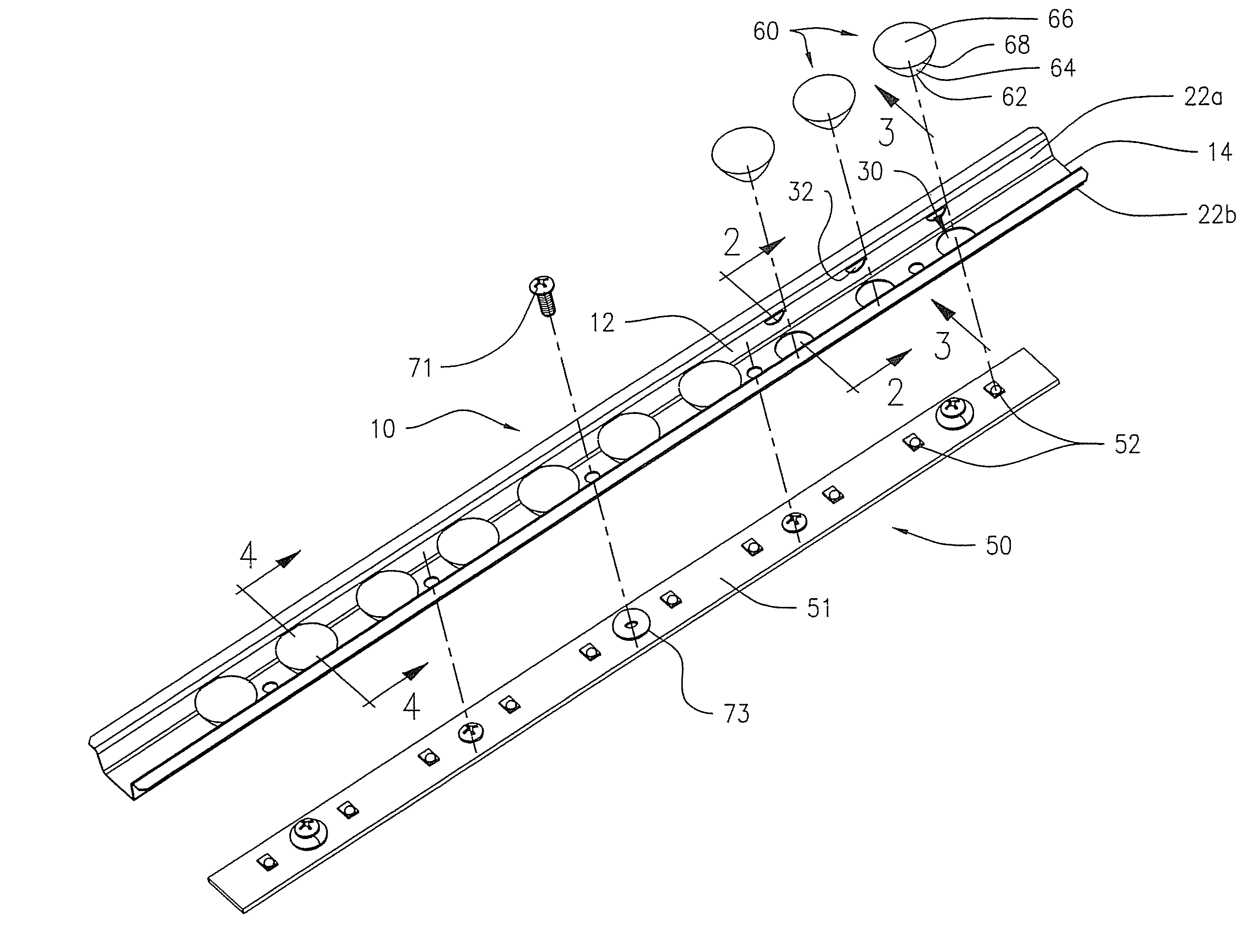
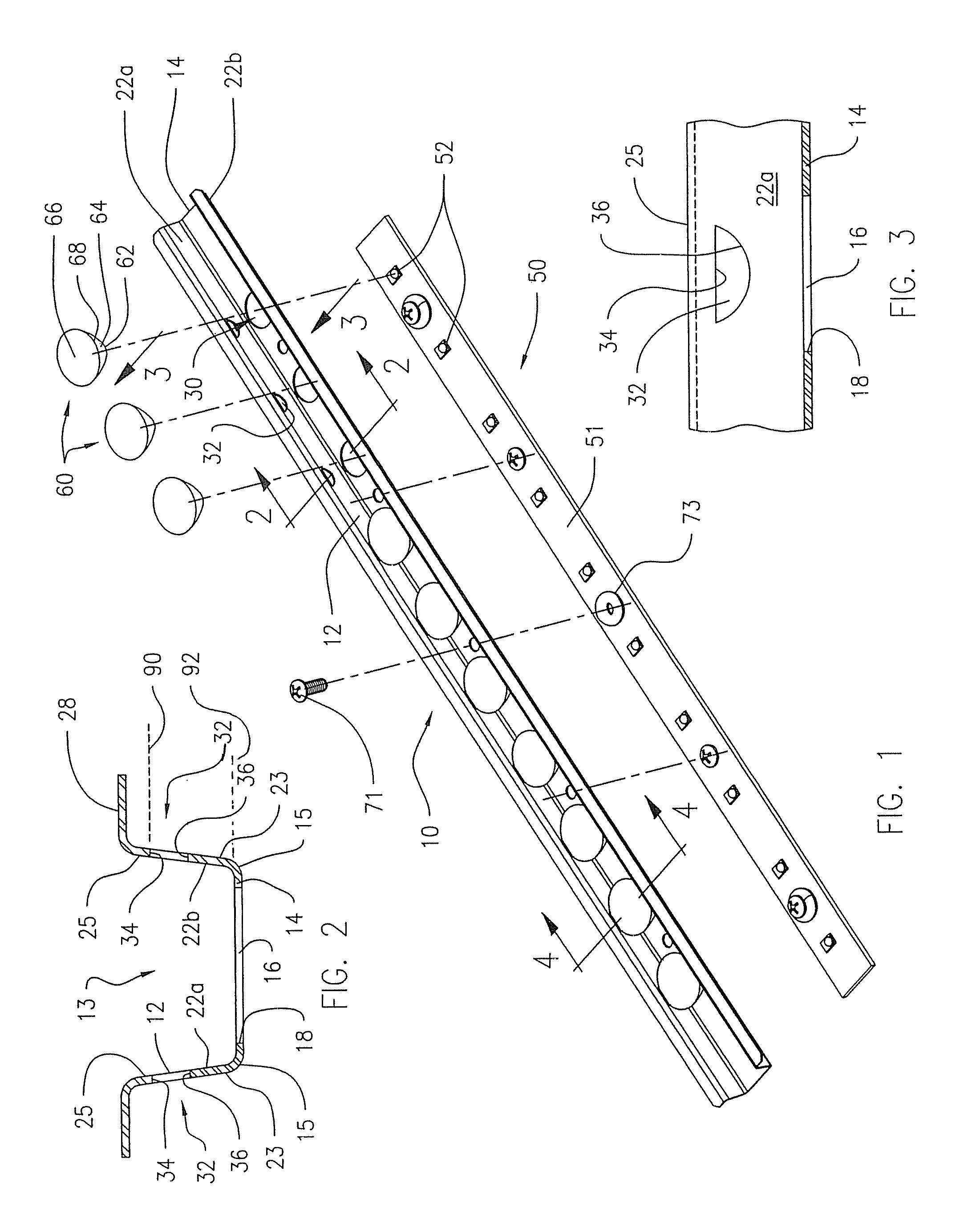
[0027]FIGS. 1-4 show the optic holding and positioning device 10, having an elongated channel member 12 that includes an elongated planar base 14, opposed first and second side edges 15, and opposed first sidewall 22a and second sidewall 22b, each sidewall having a proximal edge 23 extending from the respective first and second side edges 15 of the base 14, and a distal edge 25. The sidewalls 22a, 22b are tilted slightly outwardly. The sidewalls may, but need not, be formed integrally with the base as a unit, such as by folding a planar member (e.g. sheet metal). The base 14 and sidewalls 22a, 22b may be formed by other methods as will be evident to those of ordinary skill in the art. The device 10 also includes at least one optic holding position. Each optic holding position includes the aperture 16 formed in and through the base 14, and opposed slot openings 32 formed, one each, in the respective opposed sidewalls 22a, 22b, adjacent transversely to the aperture 16 formed in the ba...

second embodiment

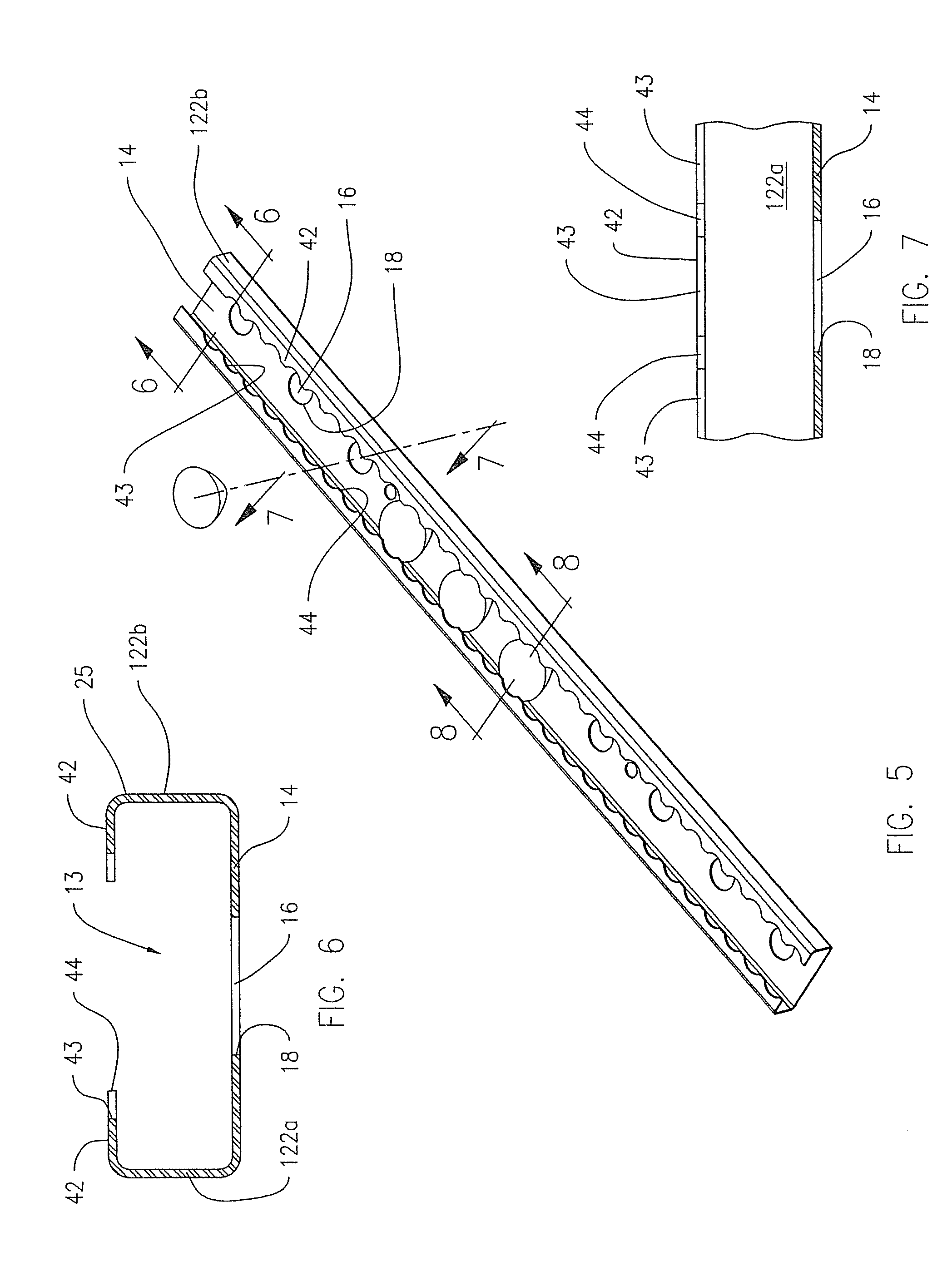
[0030]FIGS. 5-8 show the optic holding and positioning device 10, wherein the sidewalls 122a, 122b have an inwardly-extending upper flange 42 that extends from the distal edge 25 of the first and second sidewalls 122a, 122b over the rim 68 of the optic 60 and at least a portion of the light-exiting face 66 of the optic 60. The distal edge of the inwardly-extending upper flange 42 is shown having a plurality of inwardly (convexly) curved portions 43 toward the distal edge 25, separated by a plurality of outwardly extending portions 44. The inwardly (convexly) curved portions 43 conform to the curved shape of the optic rim 68, to limit the area of the light-exiting face 66 that is covered by the flange 42. The sidewalls 122a, 122b in this embodiment do not require the slot openings 32 of the embodiment of FIGS. 1-4 to restrain the optic 60 in the longitudinal +Y direction. The sidewalls 122a, 122b can be spaced apart a distance greater than the diameter of the optic rim, while retaini...


PUM


Abstract

A device for holding and positioning an optic, such as a refractive lens, over a light source such as a light emitting diode. The refractive lens is frustum-shaped with an upper light-exiting end having an upper rim, a lower light-entering end, and a conical sidewall that tapers from the upper rim to the lower end. The device has a channel including a base and first and second sidewalls extending from the opposed side edges of the base, and further having one or more optic holding positions. The optic holding position includes an aperture formed in the base that is configured to receive the conical sidewall of the optic, and an aperture formed in a portion of each sidewall, adjacent the aperture in the base, for retaining a portion of the upper rim of the optic lens. The aperture can include a slot opening through which a portion of the upper rim of the optic lens at least partially extends.

Description

FIELD OF THE INVENTION[0001]The present invention relates generally to a lighting apparatus and, more particularly, to a device for positioning optics to distributing light from one or more light sources. The present invention is particularly useful for distributing light emitted from one or more light emitting diodes (LEDs), as described herein, but is directed to distributing light generated by any type of light source.BACKGROUND OF THE INVENTION[0002]As the quality and energy efficiency of LEDs have improved, the production cost of LEDs has gone down, and LEDs are being commonly used in area lighting applications. Initial efforts to incorporating LEDs into lighting fixtures have involved retrofitting LEDs into conventional luminaires or onto or into the shape of conventional lighting lamps.[0003]Some LEDs emit light in a substantial lambertian pattern. To direct the light from such an LED, it is a usual practice to capture at least low angle light from the LED with an optic, such...

Claims


Application Information

Patent Timeline
Patent Type & Authority Applications(United States)
IPC IPC(8): F21V5/04
CPCF21S4/008F21V5/04F21V7/0091F21Y2103/003F21V19/02F21Y2101/02F21V17/164F21S4/28F21Y2103/10F21Y2115/10
Inventor BOYER, JOHN D.REED, MARK C.
Owner LSI INDS
Why Eureka
Try Eureka