
Easily assembled and detached tube connecting assembly

a technology of assembly and tube, which is applied in the direction of rod connection, fastening means, dowels, etc., can solve the problems of assembly assembly problems that are often overlooked, and achieve the effect of easy assembly and convenient disassembly

Inactive Publication Date: 2009-04-23
CHIANG CHING HUI
View PDF15 Cites 5 Cited by
  • Summary
  • Abstract
  • Description
  • Claims
  • Application Information

AI Technical Summary

Benefits of technology

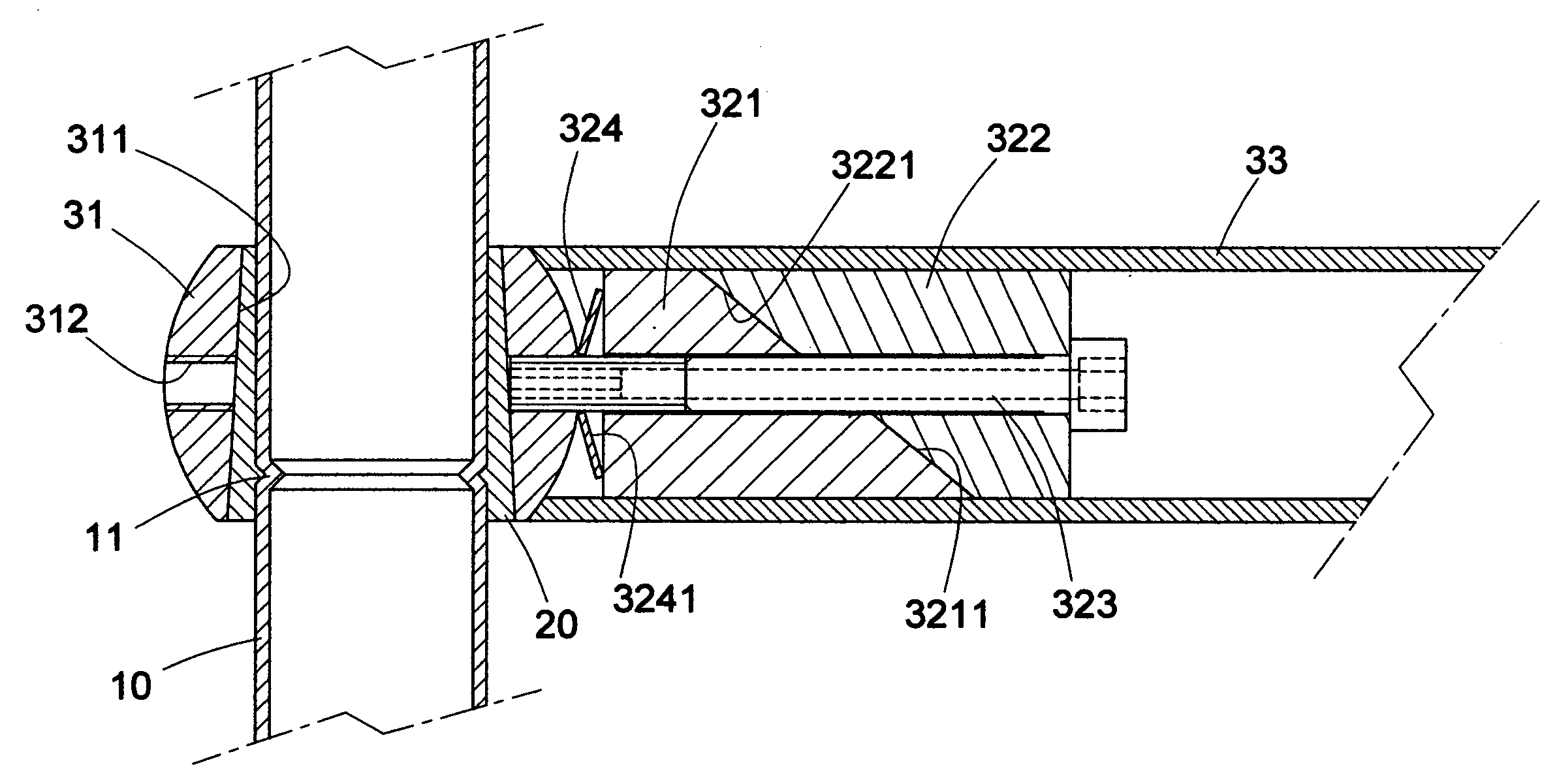
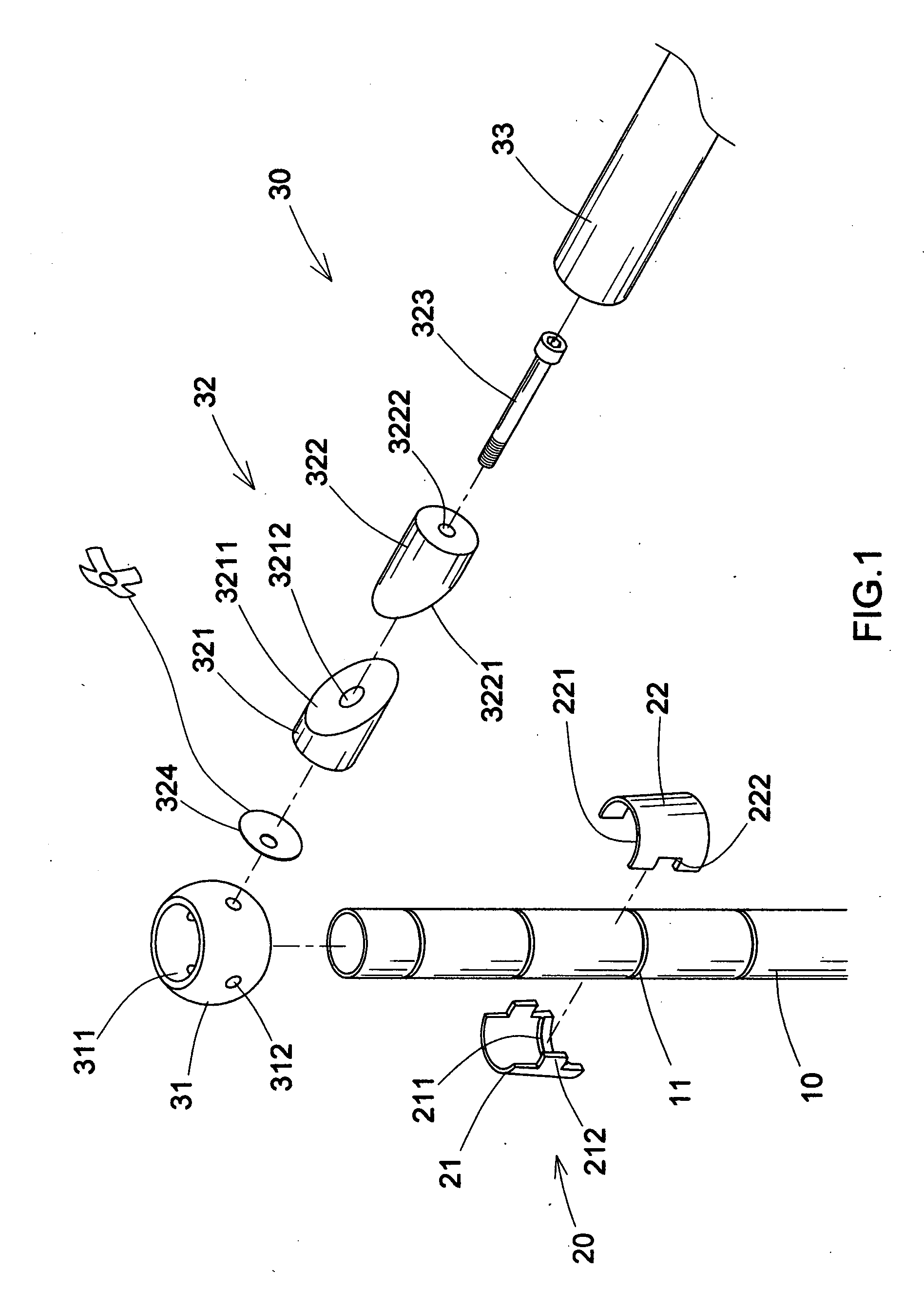
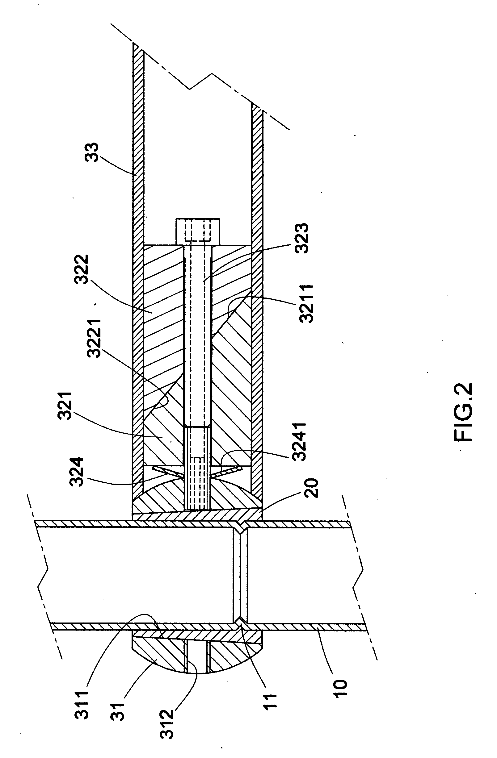
The present invention provides a tube connecting assembly that can be easily assembled and detached by the user. The assembly is tight and secure without falling out by external force. The components of the assembly are detachable and have a preferred structure that occupies a small space. The assembly includes a hollow tube, inner liners with a tapered shape, and connecting structures with screw holes and a locking unit. The assembly unit has a spherical shape and the penetrating hole has a tapered shape with a great upper portion and a small lower portion. The locking unit has slots and an elastic unit. The elastic unit is a spring or a round elastic sheet that resists against the first tightening unit. The technical effects of the present invention are easy assembly and detachment, tight and secure connection, and a compact structure.

Problems solved by technology

The prior art assembly is easy, but many problems occur in the assembly.
In the locking place, the pressure applied to the screw is not uniform so that the screw will shift and thus after assembly, the cartridge is not stable and reduce some problem in assembly.

Method used


Image

  • Easily assembled and detached tube connecting assembly
  • Easily assembled and detached tube connecting assembly
  • Easily assembled and detached tube connecting assembly

Examples


Embodiment Construction

[0029]In order that those skilled in the art can further understand the present invention, a description will be provided in the following in details. However, these descriptions and the appended drawings are only used to cause those skilled in the art to understand the objects, features, and characteristics of the present invention, but not to be used to confine the scope and spirit of the present invention defined in the appended claims.

[0030]Referring to FIGS. 1 to 3, the tube connecting assembly of the present invention is illustrated.

[0031]At least one first tube 10 each is a hollow tube. A periphery of each tube is installed with a plurality of parallel annular grooves (referring to FIG. 2).

[0032]A plurality of inner liners 20 each inner liner 20 includes a first sheet 21 and a second sheet 22 which has cambered shapes. A periphery of the inner liner 20 has a tapered shape. An interior of the inner liner 20 is formed with a convex portion 211. One side of the first sheet 21 is...


PUM


Abstract

A tube connecting assembly comprises at least one first tube; a plurality of inner liners; a periphery of each inner liner having a tapered shape; an inner periphery of each inner liner being formed with a convex portion; each inner liner enclosing a periphery of the first tube; at least one connecting structure each being formed by an assembly unit and a locking unit; the assembly unit assembled to an periphery of the first tube; the tightening unit being formed by a first tightening unit, a second tightening unit and a locking unit; each of the first tightening unit and second tightening unit has a respective inclined surface; at least one second tube enclosing the tightening unit; by screwing the locking unit, the first tightening unit and second tightening unit will engage at different orientations. The tube connecting assembly can be assembled and detached easily and conveniently.

Description

FIELD OF THE INVENTION[0001]The present invention relates to tubes, and particularly to a tube connecting assembly, which can be assembled and detached easily and conveniently so that the user can assembly the tube connecting assembly by himself or herself. The present invention has a referred tightness without falling out by external force.BACKGROUND OF THE INVENTION[0002]In the prior art cartridge, a plate has slots at a bottom surface thereof and another plate has holes at a lateral side thereof. Then screws are used to lock the two plates.[0003]The prior art assembly is easy, but many problems occur in the assembly.[0004]When screws are used to lock the plates, because the slots at the bottom of the plate are as guided holes. The user must take a great force for locking the screw to the slots. In the locking place, the pressure applied to the screw is not uniform so that the screw will shift and thus after assembly, the cartridge is not stable and reduce some problem in assembly...

Claims


Application Information

Patent Timeline
Patent Type & Authority Applications(United States)
IPC IPC(8): F16B13/04
CPCF16B7/025Y10T403/7051F16B21/16F16B7/044
Inventor CHIANG, CHING-HUI
Owner CHIANG CHING HUI
Learn More