

Shoe Tensioner for a Synchronous Belt Drive for Use With Oil
a technology of synchronous belt drive and tensioner, which is applied in the direction of belt/chain/gearing, mechanical equipment, and sleeve/sleeve tensioner, etc., can solve the problem of anomalous drive operation
- Summary
- Abstract
- Description
- Claims
- Application Information
AI Technical Summary
Benefits of technology
Problems solved by technology
Method used
Image

Examples
Embodiment Construction
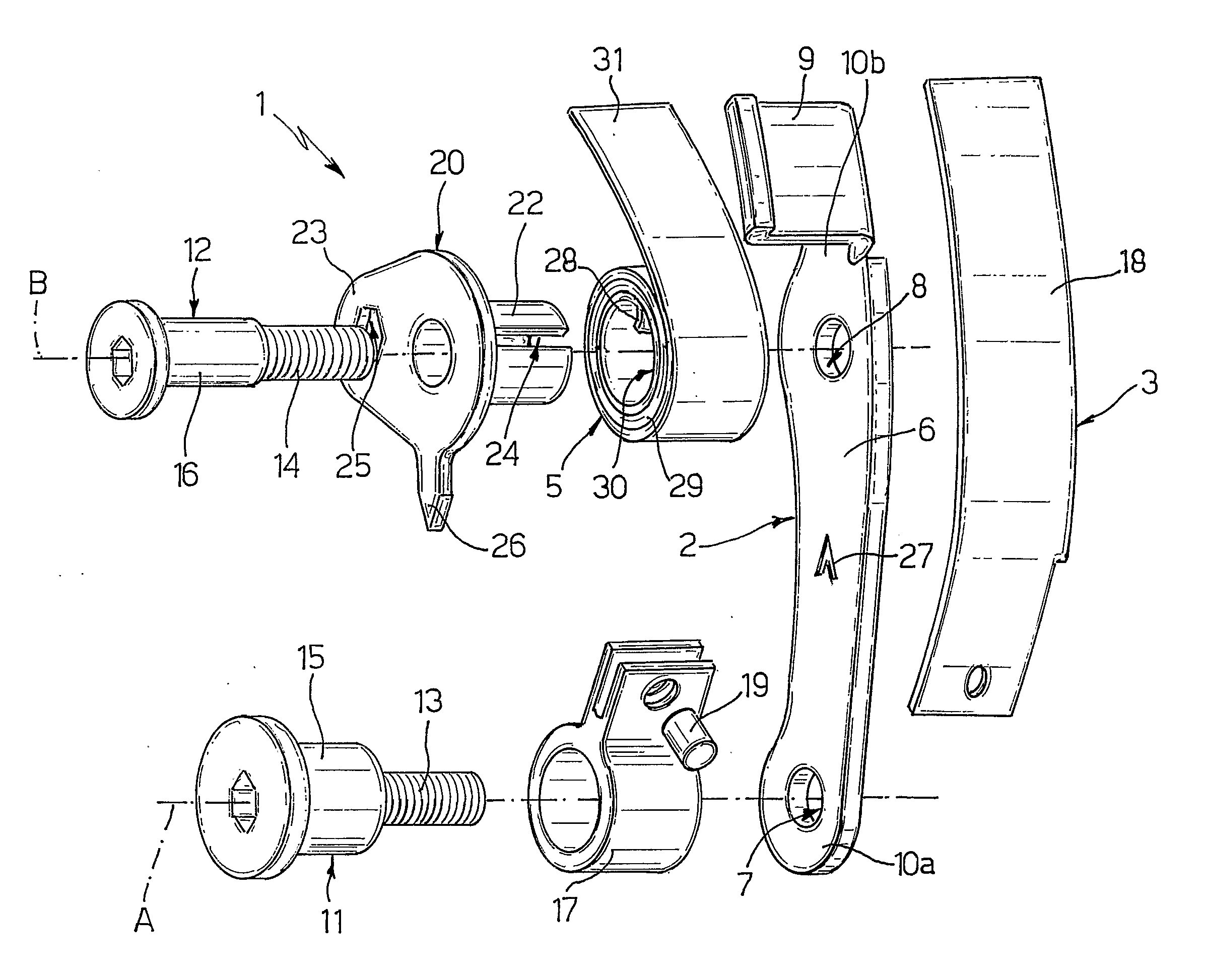
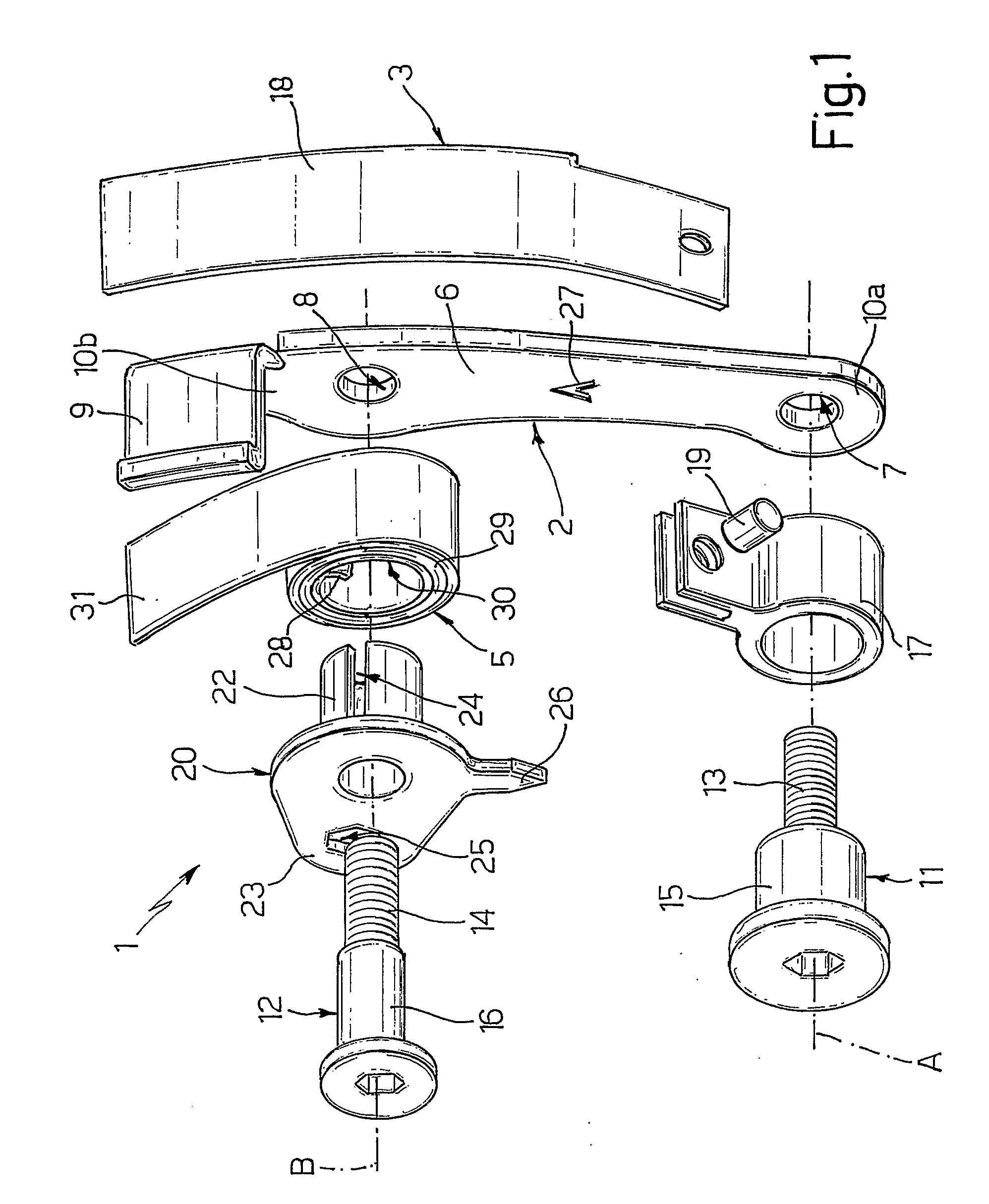
[0011]FIG. 1 shows a shoe tensioner 1 comprising an elongated support 2 adapted to be connected rigidly to a wall of an internal combustion engine (not shown); a guide member 3 adapted to cooperate with a toothed belt 4 for an in-oil, e.g. timing drive, application; and a spiral spring 5 which cooperates with guide member 3 to tension toothed belt 4.
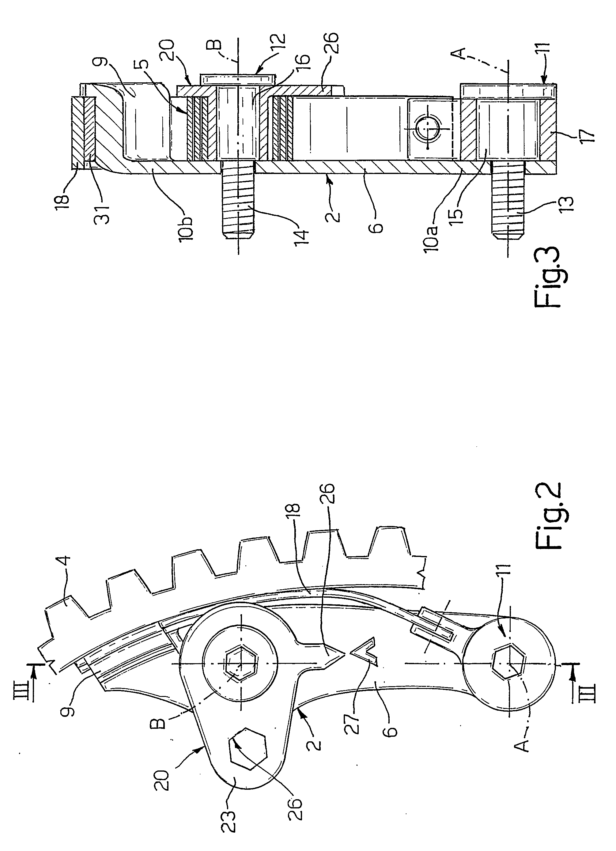
[0012]More specifically, elongated support 2 comprises, integrally, a plate 6 defining two holes 7, 8; and a bent bracket 9 located on the opposite side of guide member 3 to toothed belt 4 and defining a fixed stop for guide member 3. At opposite ends, plate 6 comprises a first end portion 10a defining hole 7; and a second end portion 10b connected to bracket 9 and defining hole 8.
[0013]Elongated support 2 is connected to the internal combustion engine wall by two screws 31, 12 housed respectively inside holes 7, 8 and comprising respective threaded portions 13, 14, and respective cylindrical centering portions 15, 16.
[0014]Centering por...
PUM
 Abstract
Description
Claims
Application Information