
Sensors For Estimating Properties Of A Core

a technology of cores and sensors, applied in the field of cores for estimating properties, can solve the problems of not being conducive to continuous coring (coring beyond the core barrel length) or to taking measurements

Inactive Publication Date: 2009-04-23
BAKER HUGHES INC
View PDF51 Cites 71 Cited by
  • Summary
  • Abstract
  • Description
  • Claims
  • Application Information

AI Technical Summary

Benefits of technology

The present patent provides systems, apparatus, and methods for continuous or substantially continuous coring of a subsurface formation. This involves drilling into a formation to retrieve a core, receiving the core into a chamber, and removing a portion of the core uphole of the open end of the chamber so as to continue to receive the core as the drilling continues. The systems and methods allow for continuous coring operations and selectively storing core samples obtained at different formation depths. Additionally, the patent provides methods for estimating a property of a core and performing tomography of a continuously obtained core using at least one sensor placed proximate to the core.

Problems solved by technology

Such systems, therefore, are not conducive to continuous coring (coring beyond the core barrel length) or for taking measurements of cores longer than the core barrel length.

Method used


Image

  • Sensors For Estimating Properties Of A Core
  • Sensors For Estimating Properties Of A Core
  • Sensors For Estimating Properties Of A Core

Examples


Embodiment Construction

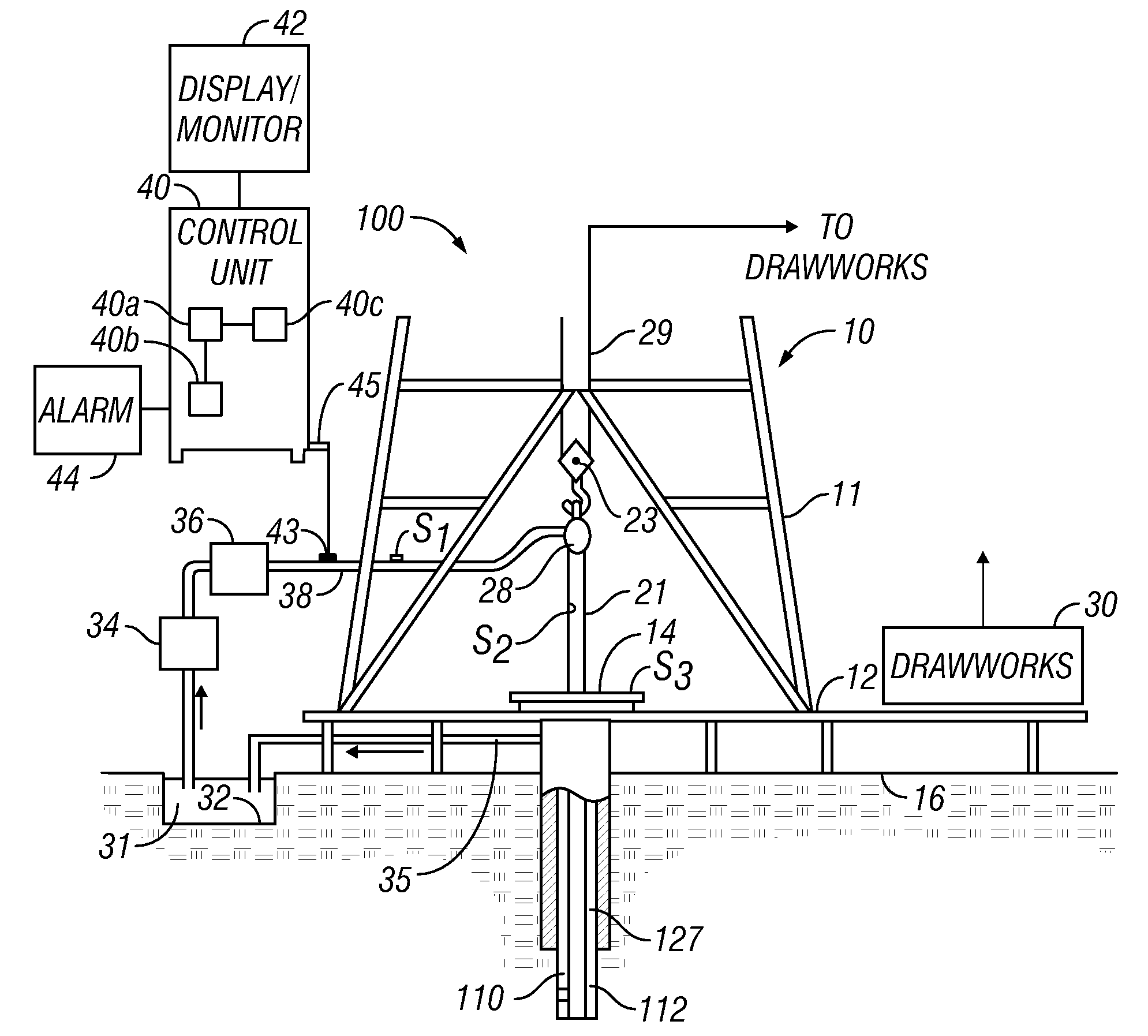
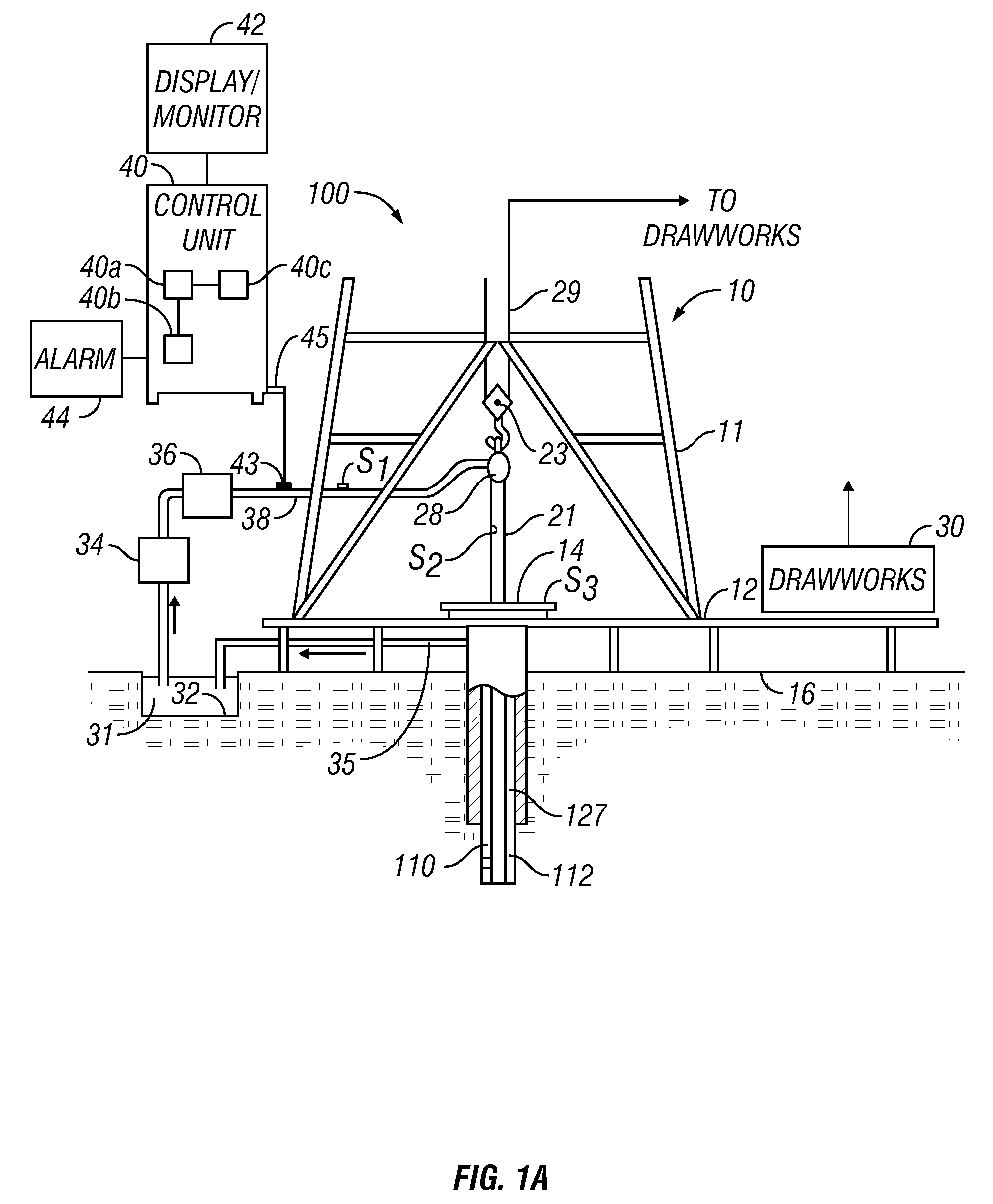
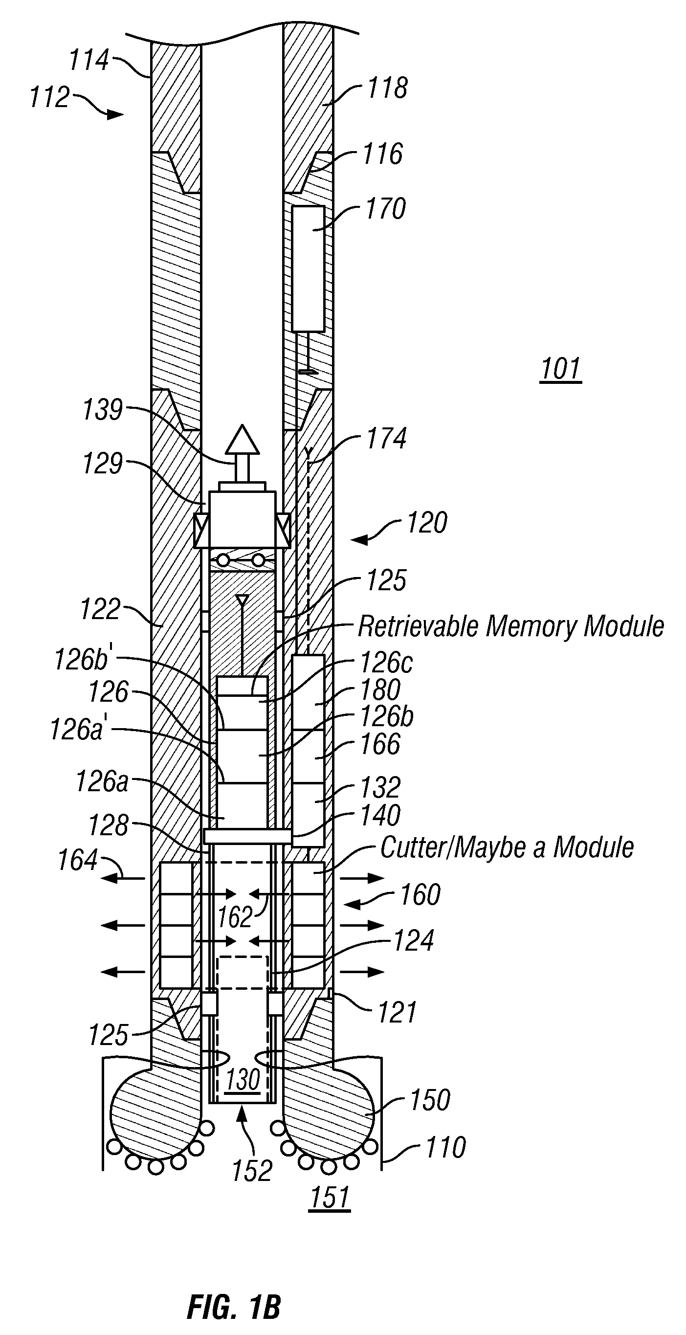
[0023]FIG. 1 (comprising FIGS. 1A and FIG. 1B) is a schematic diagram showing an exemplary drilling system 100 that may be utilized for continuous coring, selectively storing core samples, estimating one or more properties of the core and / or estimating formation parameters during drilling of a wellbore 110 according to one aspect of the disclosure. FIG. 1 shows a wellbore 110 being drilled with a drill string 112 in a formation 101. The drill string 112, in one aspect, includes a tubular member 114 and a drilling assembly 120, also referred to as a “bottomhole assembly” or “BHA” attached at its bottom end 118 with a suitable connection joint 116. The tubular member 114 is typically made up by connecting drill pipe sections. A drill bit 150 (also referred to herein as the “coring bit”) is attached to the bottom end 121 of the drilling assembly 120 for drilling the wellbore 110 in the formation 101. The drill bit 150 has a through bore or mouth 152 having a diameter substantially equa...


PUM


Abstract

A method for estimating a property downhole is provided, which, in one aspect, may include receiving a core at a receiving end of a downhole tool while removing a portion of the received core distal from the receiving end of the tool, obtaining measurements by a sensor downhole, and processing the measurements to estimate the property of interest.

Description

CROSS-REFERENCE TO RELATED APPLICATIONS[0001]This application takes priority from U.S. Provisional Patent Application Ser. No. 60 / 975,065, filed on Sep. 25, 2007.BACKGROUND OF THE DISCLOSURE[0002]1. Field of the Disclosure[0003]The disclosure herein relates generally to obtaining cores from a formation and estimating one or more properties of interest downhole.[0004]2. Description of the Related Art[0005]To obtain hydrocarbons such as oil and gas, wells (also referred to as “wellbores” or “boreholes”) are drilled by rotating a drill bit attached at a bottom end of a drill string. The drill string typically includes a tubular member (made by joining pipe sections) attached to a top end of a drilling assembly (also referred to as the “bottomhole assembly” or “BHA”) that has a coring drill bit (or “coring bit”) at the bottom end of a drilling assembly. The coring bit has a through-hole or mouth of a selected diameter sufficient to enable the core to enter into a cylindrical coring barr...

Claims


Application Information

Patent Timeline
Patent Type & Authority Applications(United States)
IPC IPC(8): G01V3/14G01V3/00G01V5/04
CPCE21B25/10E21B25/16E21B47/00E21B25/00E21B49/00E21B49/02
Inventor CASTILLO, HOMERO C.GEORGI, DANIEL T.PATTERSON, DOUGLAS J.HALL, LARRY M.GOLD, RANDYREIDERMAN, ARCADY
Owner BAKER HUGHES INC
Learn More