Method for detecting problematic disk drives and disk channels in a RAID memory system based on command processing latency

a raid memory system and disk channel technology, applied in error detection/correction, functional testing, instruments, etc., can solve problems such as failure of disk drive mechanisms, failure of electrical components such as motors and servos, and disk drives may degrad

Active Publication Date: 2009-04-23
DATADIRECT NETWORKS
View PDF14 Cites 30 Cited by
  • Summary
  • Abstract
  • Description
  • Claims
  • Application Information

AI Technical Summary

Benefits of technology

[0016]It is therefore an object of the present invention to provide a method for e...

Problems solved by technology

Disk drives may degrade and their failure in large storage systems cause serious problems.
Such failures are usually attributed to the defects in the recording media, failure in the mechanics of the disk drive mechanisms, failure in electrical components such as motors and servors, and failure in the electronic devices which are a part of the disk drive units, as well as a number of other attributable causes.
During the normal operation of disk drives whether now or previously operational such disk drives may have a number of failure modes which have been identified by the disk drive industry.
Some failure modes initially present themselves as an inability to read and/or write data.
Some of the errors are the result of medium errors on magnetic disk platters, the surface of which can no longer retain its magnetic state.
As the density of data per square inch of information carriers such as disks, has increased greatly over the years, the susceptibility to errors caused by physical defects has become a greater problem t...

Method used


Image

  • Method for detecting problematic disk drives and disk channels in a RAID memory system based on command processing latency
  • Method for detecting problematic disk drives and disk channels in a RAID memory system based on command processing latency
  • Method for detecting problematic disk drives and disk channels in a RAID memory system based on command processing latency

Examples


Embodiment Construction

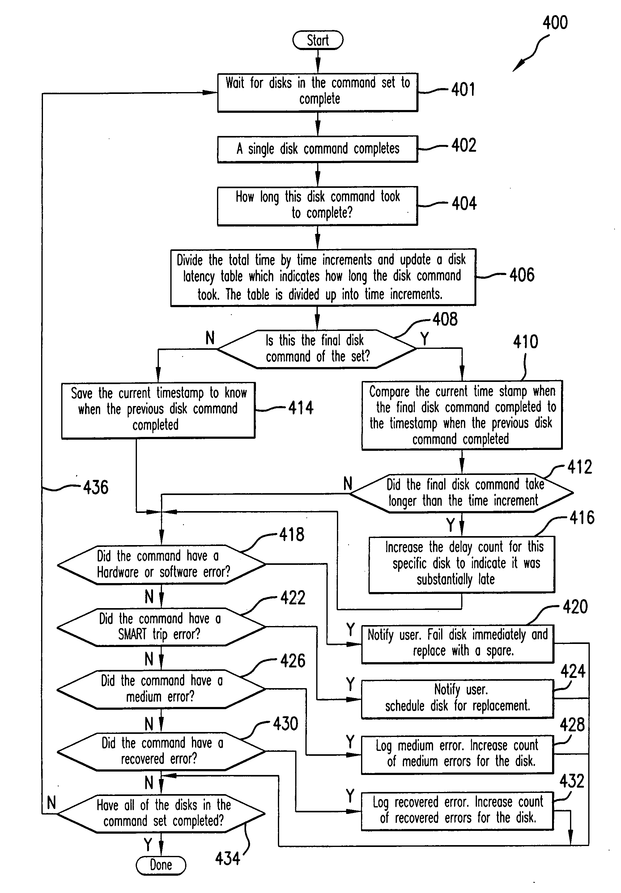
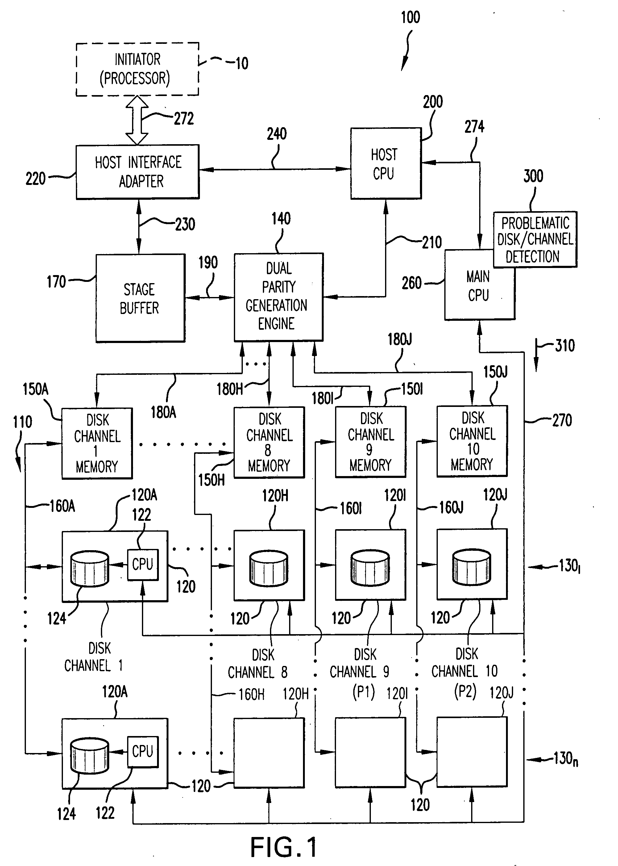
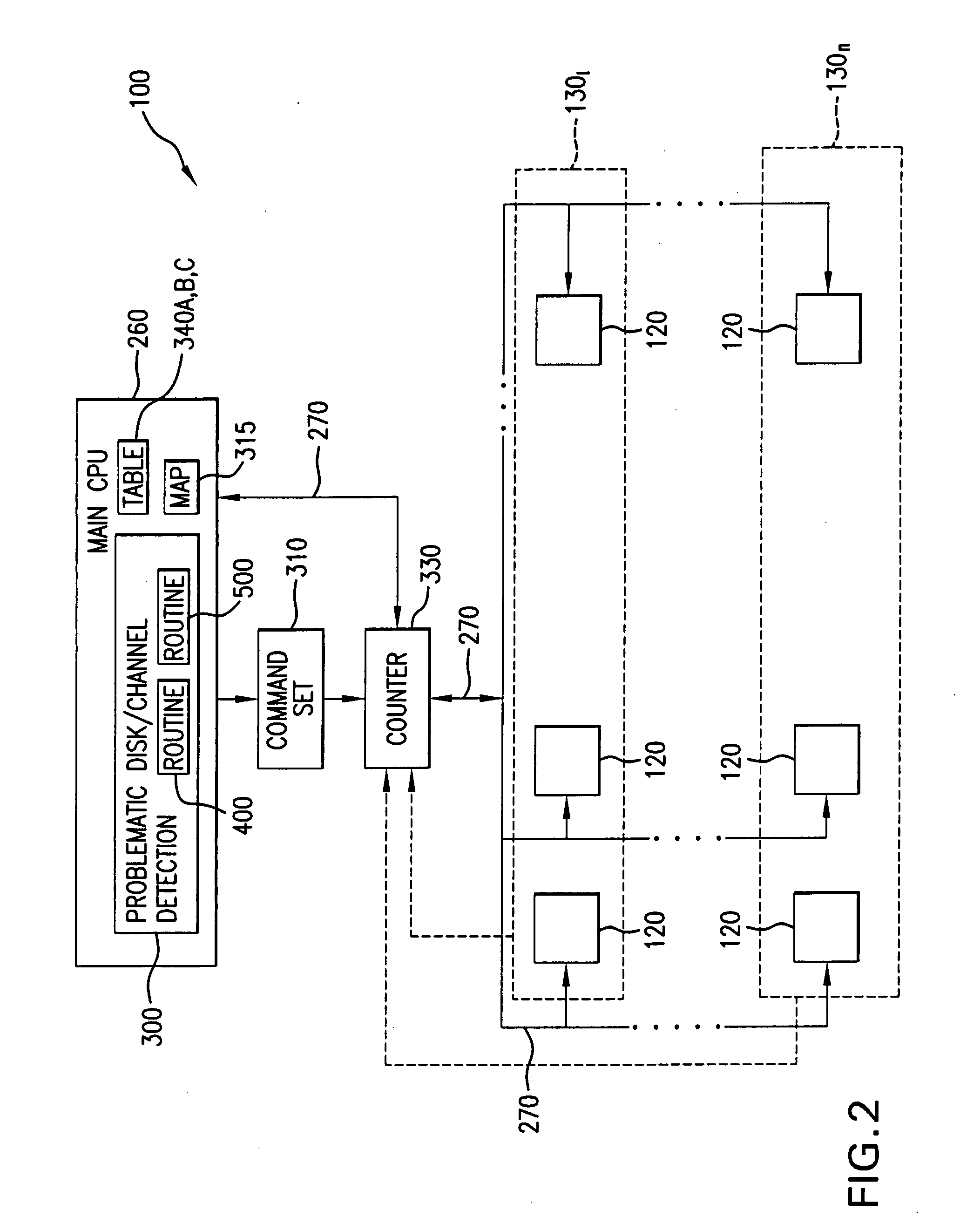
[0033]Referring now to FIG. 1, there is shown memory system 100 for storing and retrieving data for use by one or more processors (initiators) 10. Although not restricted to any particular redundant array of independent disks (RAID), the capability of the memory system 100 to detect problematic disks is illustrated herein in conjunction with a RAID memory system, for example RAID 3 / 6, having multithreaded parallel architecture described in detail in further paragraphs.

[0034]Memory system 100 includes a multidimensional array 110 of disk storage devices 120 distributed in read / write tier groups 1301-130n for storing data and parity values corresponding to the data stored in the array. Each tier group 1301-130n in the array 110 constitutes a multiplicity of data disk storage channels 1-8 which in the example illustrated herein, is formed by eight disk drives 120A-120H.

[0035]For simplicity, the following description pertains to the tier group 1301. However, the principles of design and...


PUM


Abstract

In order to detect problematic drives in random arrays of independent disks, the system measures the latency of executing command sets which are broadcast to all disks in the data storage system and the results are compared to identify which disks take substantially longer to complete the requests. Disks that take longer to complete requests are likely to be problematic and are candidates for further examination and replacement. The disks in each tier group are compared to determine if any disk in that group exhibits problems. Also, counters for each tier group are compared to determine if the problem is with the disk or with the channel of the tier group. The latency of each disk in the tier group is saved in a table to provide a histogram of the latency of the disks in the tier group. Histograms of the disks in a single tier group are compared to determine if a specific disk is problematic. Histograms of each tier group are compared to determine if a specific disk is problematic or all the disks on the same channel exhibit problems.

Description

FIELD OF THE INVENTION[0001]The present invention relates in general to data processing systems, and in particular, to prediction of disk drives failure in data storage systems.[0002]More in particular, the present invention is directed to detection of problematic disks (disk drives) at an early stages of degradation, so that the detected problematic disks may be scheduled for replacement before their failure in order to prevent degradation of the overall performance and / or reliability of a data storage system.[0003]Additionally, the present invention takes advantage of measuring the latency of executing a command set broadcast to all of the disks of the storage system simultaneously and comparing the results to identify the disk drives which take substantially longer to complete the requests. Such disk drives are considered likely to be problematic and are candidates for further examination and replacement.[0004]Still further, the present invention is directed to detecting problema...

Claims


Application Information

Patent Timeline
IPC IPC(8): G06F11/26
CPCG06F11/008G06F11/1076G06F2211/1057
Inventor PISZCZEK, MICHAELMANNING, J. GORDONPONTOS, THOMAS
Owner DATADIRECT NETWORKS
Why Eureka
Try Eureka