

Seating sensor
a sensor and seat technology, applied in the field of seat sensors, can solve the problems of increased cost, incorrect sensing of the seat of the occupant, and possible causes of incorrect sensing, so as to reduce the overall cost of the seat and the sensor, accurate sensing, and reduce the possibility of incorrect sensing
- Summary
- Abstract
- Description
- Claims
- Application Information
AI Technical Summary
Benefits of technology
Problems solved by technology
Method used
Image

Examples
first embodiment
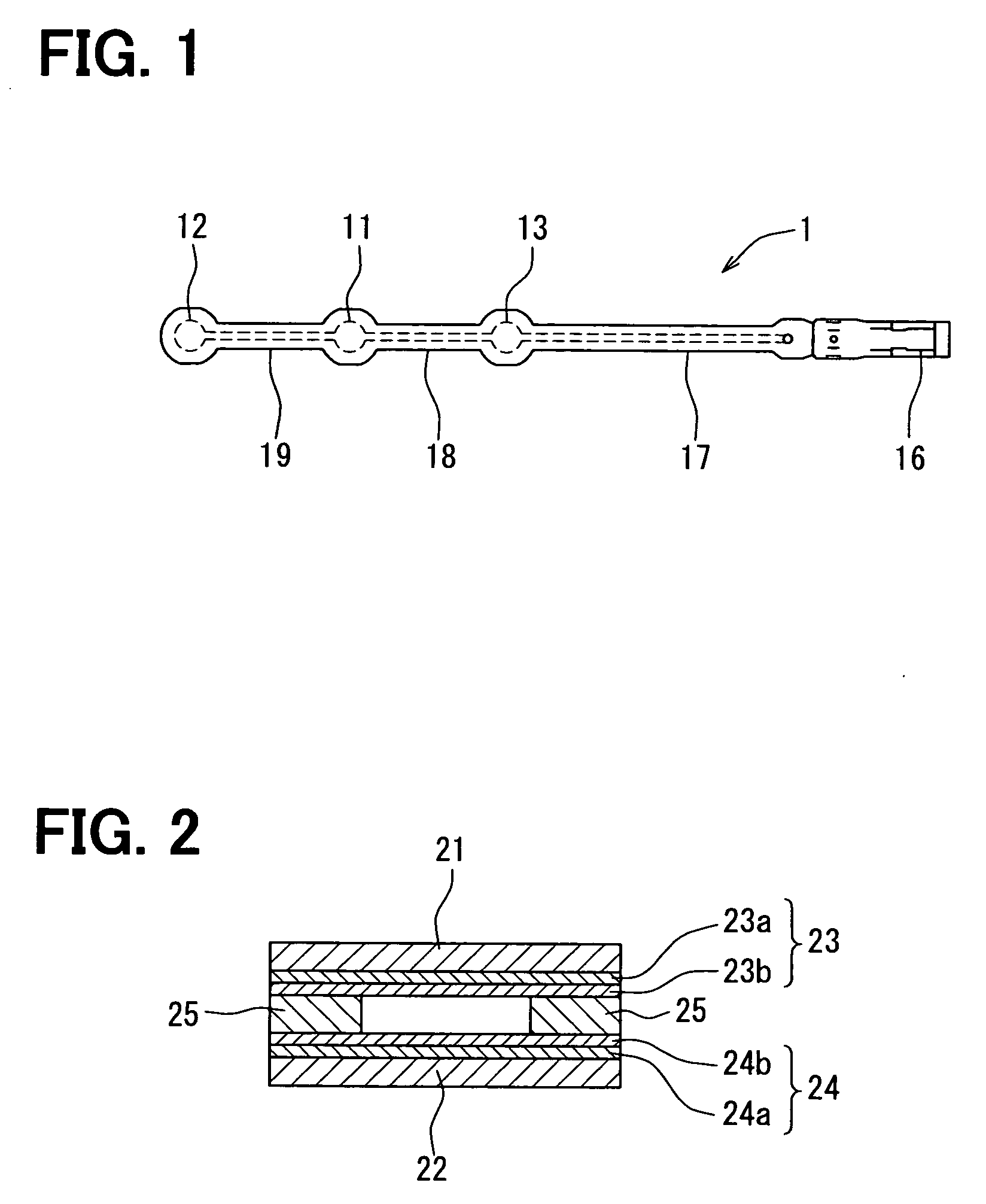
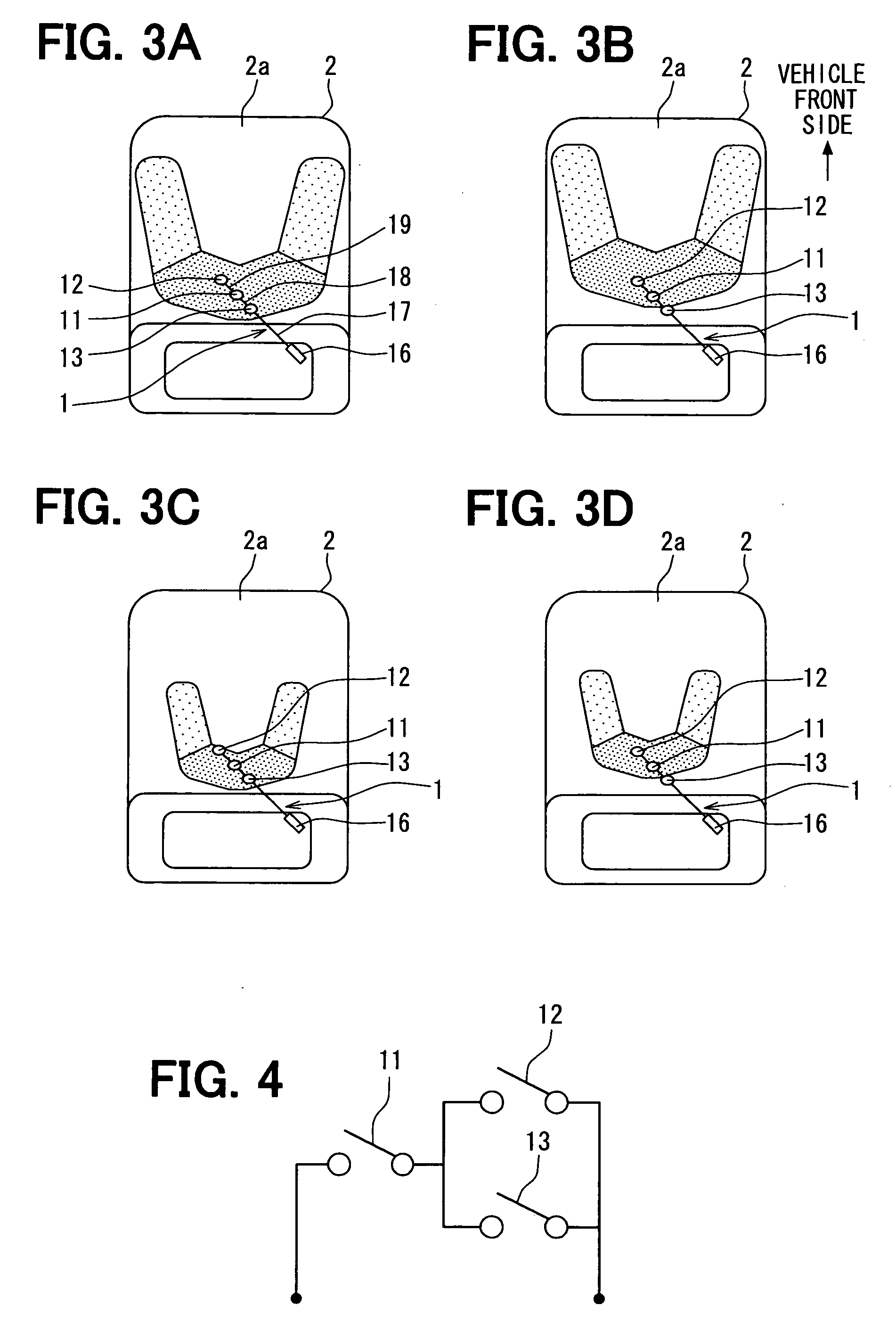
[0056]Various exemplary embodiments will now be introduced. Referring to FIG. 1 to FIG. 4, a seating sensor 1 of a first embodiment will be described below. FIG. 1 is a plan view of the seating sensor 1. FIG. 2 is a sectional enlarged view of a region of a sensor cell 11 of the seating sensor 1. FIG. 3 are plan views of a state in which the seating sensor 1 is mounted in a vehicle seat 2, that is, views of the seating sensor 1 seen from above a vehicle. FIG. 4 is a circuit diagram of the seating sensor 1.
[0057]As shown in FIG. 1, the seating sensor 1 includes three sensor cells 11, 12, and 13, a connector 16, and conducting members 17, 18, and 19 that link the respective sensor cells 11 to 13 and the connector 16. The sensor cells 11 to 13 function as switches that conduct when incurring a load due to an occupant or a piece of luggage. The connector 16 includes two terminals connected to the sensor cells 11 to 13 over the conducting members 17 to 19, and is connected to an occupant ...
second embodiment
[0083]Next, a seating sensor 100 of a second embodiment will be described with reference to FIG. 5 and FIG. 6. FIG. 5 is a plan view of a state in which the seating sensor 100 is mounted in the vehicle seat 2. FIG. 6 is a circuit diagram of the seating sensor 100. The same reference numerals will be assigned to components identical to those of a first embodiment, and a description will be omitted.
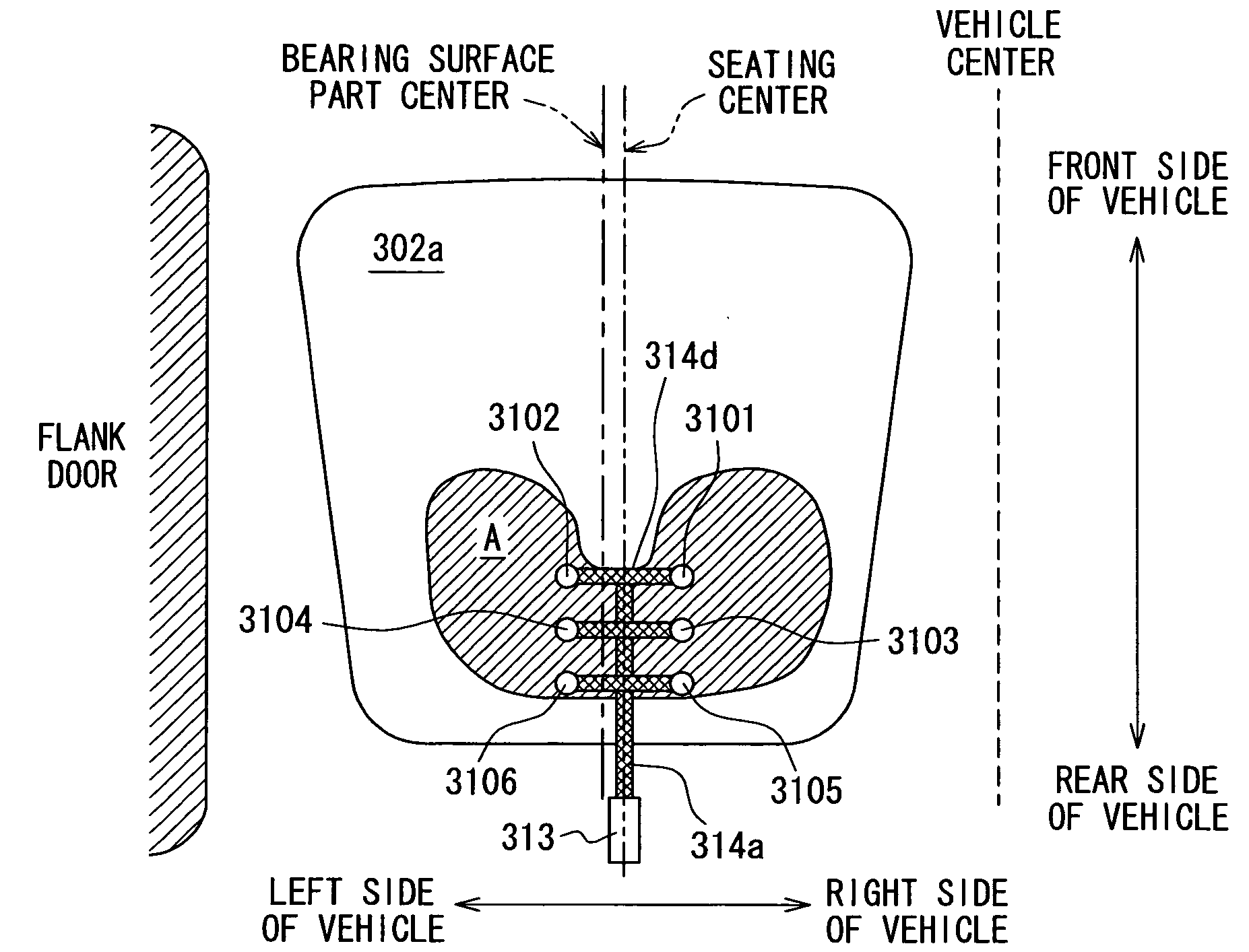
[0084]As shown in FIG. 5, the seating sensor 100 includes five sensor cells 101, 102, 103, 104, and 105, a connector 16, and a conducting member 107. The sectional construction of the seating sensor 100 is identical to that of the seating sensor 1 of a first embodiment.
[0085]The second sensor cell 102 is located at a position toward the front side and to the left side of the vehicle from the position of the first sensor cell 101. The third sensor cell 103 is located at a position toward the front side and to the right side of the vehicle from the position of the first sensor cell 101. The f...
third embodiment
[0088]Next, a seating sensor 200 of a third embodiment will be described with reference to FIG. 7 and FIG. 8. FIG. 7 is a plan view of a state in which the seating sensor 200 is mounted in the vehicle seat 2. FIG. 8 is a circuit diagram of the seating sensor 200. The same reference numerals will be assigned to components identical to those of a first embodiment, and a description will be omitted.
[0089]As shown in FIG. 7, the seating sensor 200 includes six sensor cells 201, 202, 203, 204, 205, and 206, a connector 16, and a conducting member 207. The sectional construction of the seating sensor 200 is identical to that of the seating sensor 1 of a first embodiment.
[0090]The second sensor cell 202 is located at a position toward the front side and to the right side of the vehicle from the position of the first sensor cell 201 or a generally central position of the group of sensor cells. The third sensor cell 203 is located at a position toward the rear side and to the right side of t...
PUM
 Abstract
Description
Claims
Application Information