

Electronic imaging apparatus
- Summary
- Abstract
- Description
- Claims
- Application Information
AI Technical Summary
Benefits of technology
Problems solved by technology
Method used
Image

Examples
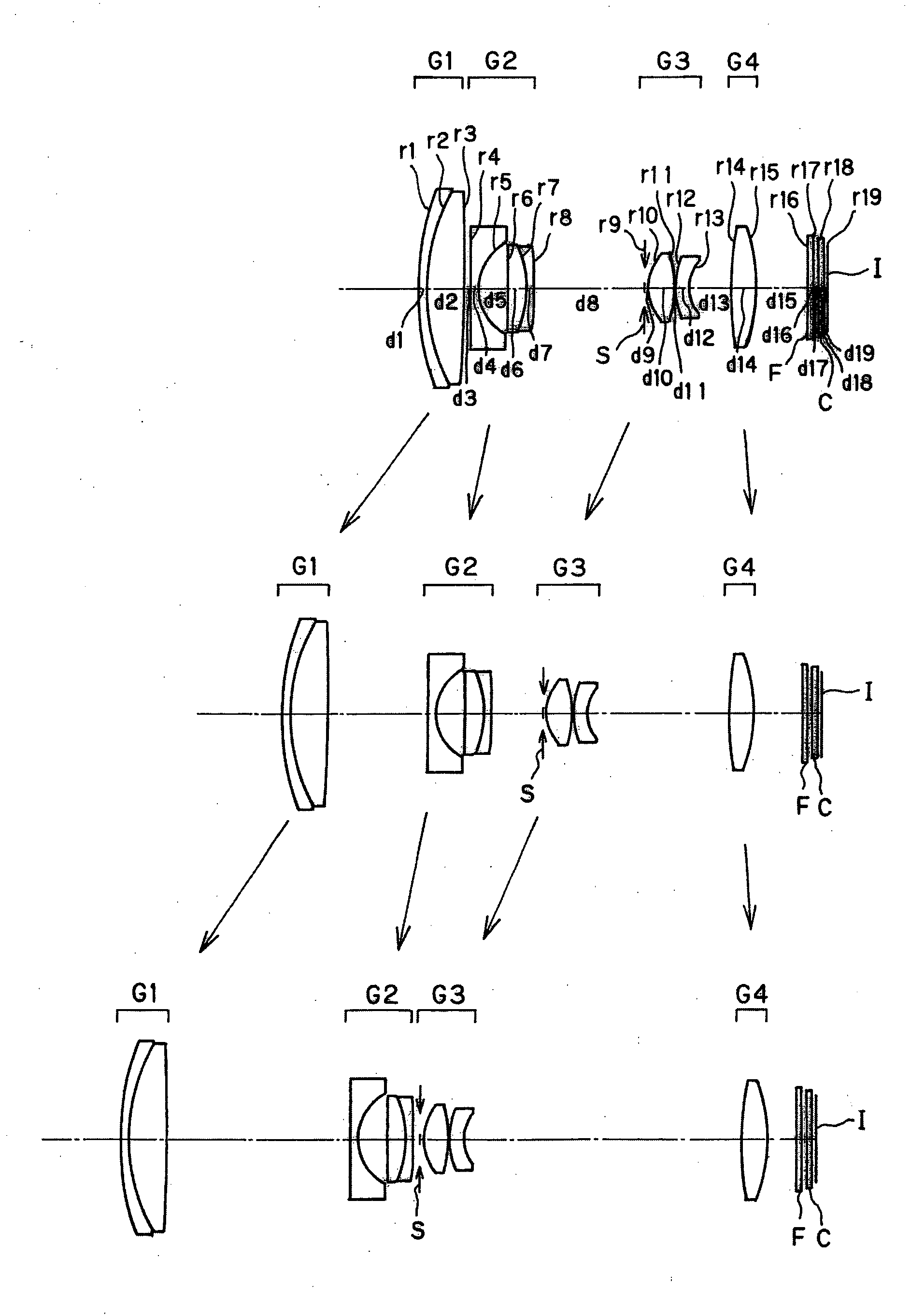
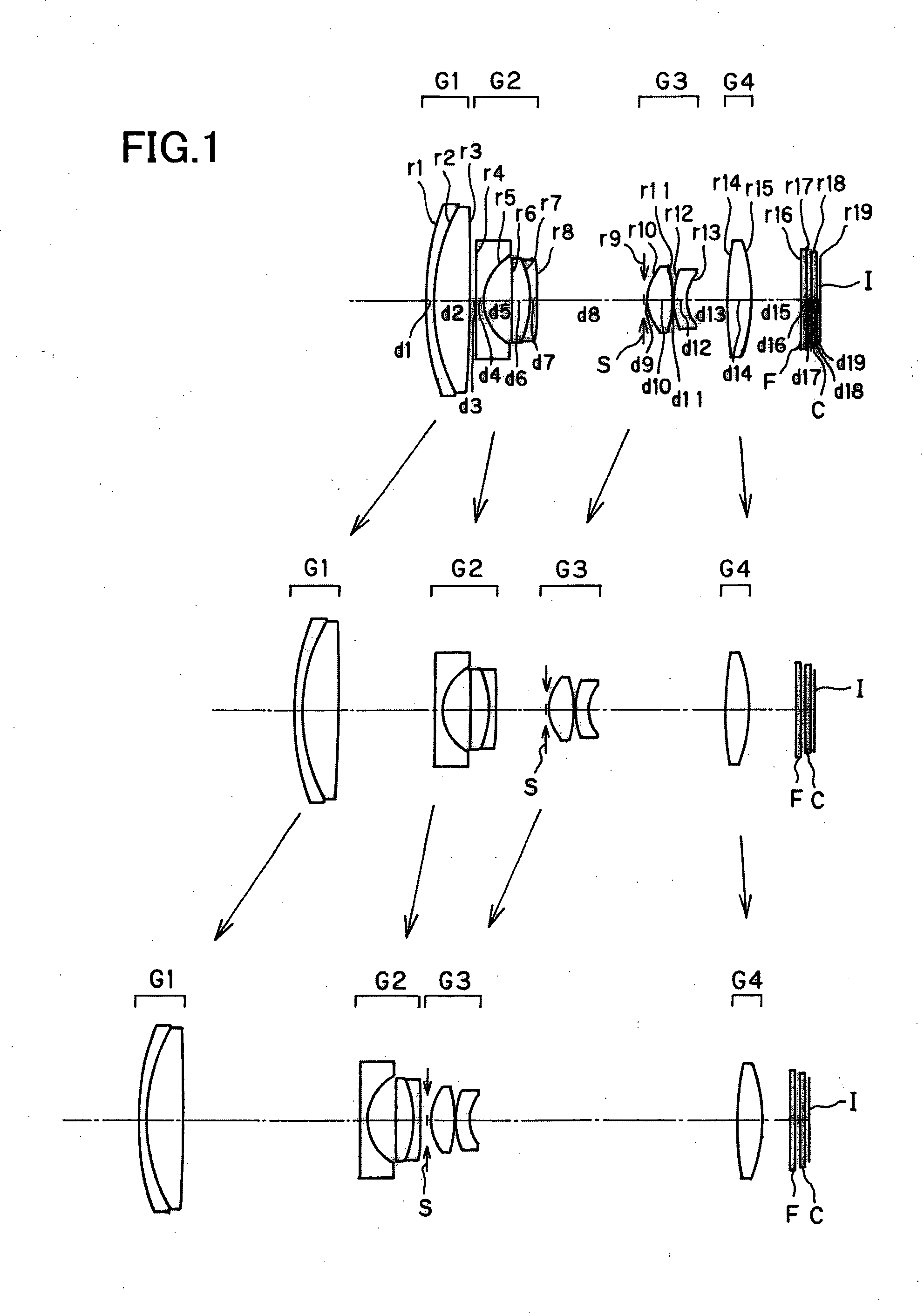
numerical example 1
[0144]
Unit mmSurface dataSurface No.rdndνd 126.6660.801.9228618.90 219.2503.501.7432049.34 3 (Aspheric surface)−176.734Variable 4 (Aspheric surface)−40.9590.801.8061040.92 5 (Aspheric surface)5.5282.69 6−1141.8381.711.9459517.98 7−10.8620.701.8061040.92 8 (Aspheric surface)134.158Variable 9 (Stop)∞0.3010 (Aspheric surface)4.2982.401.4970081.5411 (Aspheric surface)−11.6970.10128.0621.302.0017020.6413 (Aspheric surface)4.214Variable1440.8032.201.7432049.3415 (Aspheric surface)−16.732Variable16∞0.401.5477162.8417∞0.5018∞0.501.5163364.1419∞0.37Image plane∞Aspheric surface data3rd surfaceK = 0.000, A4 = 7.63091E−06, A6 = −4.82260E−094th surfaceK = 0.000, A4 = 1.32148E−03, A6 = −5.72963E−05, A8 = 1.18744E−06,A10 = −1.03698E−085th surfaceK = 0.000, A4 = 1.61134E−03, A6 = 2.28101E−05, A8 = −1.71055E−06,A10 = −1.22624E−098th surfaceK = 0.000, A4 = −4.56444E−04, A6 = −9.41345E−06,A8 = −1.00141E−07, A10 = −2.44141E−1010th surfaceK = 0.000, A4 = −1.33244E−03, A6 = −5.69354E−05,A8 = −2.91994E−06...
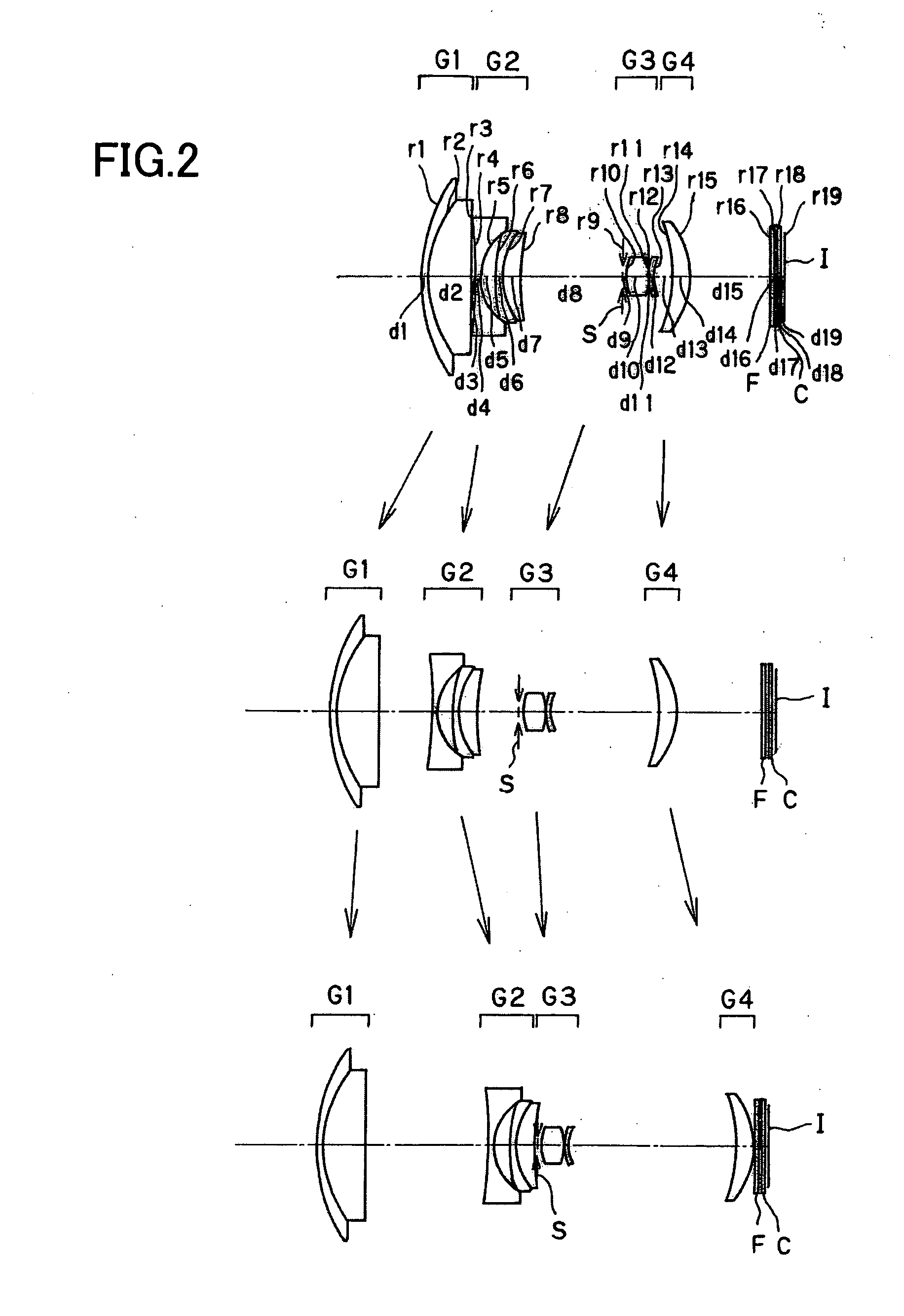
numerical example 2
[0145]
Unit mmSurface dataSurface No.rdndνd 116.4680.601.9459517.98 211.6694.001.7725049.60 3 (Aspheric surface)−298.514Variable 4 (Aspheric surface)−35.6940.501.8348142.71 5 (Aspheric surface)5.2501.50 6 (Aspheric surface)41.1850.501.7725049.60 76.7001.601.9459517.98 821.527Variable 9 (Stop)∞0.3010 (Aspheric surface)4.0992.051.4970081.5411 (Aspheric surface)−10.6340.10124.9960.402.0017020.64133.471Variable14 (Aspheric surface)−10.0821.601.7432049.3415 (Aspheric surface)−5.932Variable16∞0.301.5477162.8417∞0.3018∞0.301.5163364.1419∞0.37Image plane∞Aspheric surface data3rd surfaceK = 0.000, A4 = 2.79166E−05, A6 = −9.61223E−084th surfaceK = 0.000, A4 = 6.02597E−04, A6 = −3.67937E−05, A8 = 9.10591E−07,A10 = −7.79624E−095th surfaceK = 0.000, A4 = 6.24667E−04, A6 = 6.02647E−05, A8 = −2.20783E−06,A10 = −1.71665E−086th surfaceK = 0.000, A4 = 9.33860E−04, A6 = 3.93633E−0510th surfaceK = 0.000, A4 = −2.44420E−03, A6 = −1.76979E−05,A8 = −3.79600E−06, A10 = −7.36605E−0811th surfaceK = 0.000, A4 ...
numerical example 3
[0146]
Unit mmSurface dataSurface No.rdndνd 120.9090.802.0017020.64 216.7203.621.6188163.85 3 (Aspheric surface)−99.283Variable 4 (Aspheric surface)−76.5280.801.8348142.71 5 (Aspheric surface)7.1332.58 6−206.9231.632.1022516.79 7−18.6400.801.8348142.71 8 (Aspheric surface)54.142Variable 9 (Stop)∞0.3010 (Aspheric surface)5.5932.491.6935053.2111 (Aspheric surface)−19.4730.08125.5721.461.4970081.541337.0890.712.0033028.27143.573Variable15 (Aspheric surface)32.8253.001.7433049.3316 (Aspheric surface)−14.479Variable17∞0.401.5477162.8418∞0.5019∞0.501.5163364.1420∞0.37Image plane∞Aspheric surface data3rd surfaceK = 0.000, A4 = 1.14689E−05, A6 = 4.83606E−09, A8 = −2.02752E−10,A10 = 7.85884E−134th surfaceK = 9.178, A4 = 8.86386E−05, A6 = −2.97753E−06, A8 = 4.62415E−08,A10 = −3.04205E−105th surfaceK = 0.265, A4 = 1.50448E−04, A6 = 6.43712E−06, A8 = −2.33528E−07,A10 = −2.66160E−098th surfaceK = −1.493, A4 = −3.07535E−04, A6 = −4.47187E−06,A8 = 2.37774E−07, A10 = −5.43727E−0910th surfaceK = 0.82...
PUM
 Abstract
Description
Claims
Application Information