Projection lens and projector

a projection lens and projector technology, applied in the field of projection lenses, can solve the problems of increased production cost, difficult to obtain optimal lens arrangement, increased etc., and achieve the effect of sufficient correction of lateral chromatic aberration, and less number of lens elements

Active Publication Date: 2009-12-31
KONICA MINOLTA OPTO
View PDF4 Cites 8 Cited by
  • Summary
  • Abstract
  • Description
  • Claims
  • Application Information

AI Technical Summary

Benefits of technology

[0020]In view of the above, it is an object of the present invention to provide a projection lens capable of sufficiently correcting lateral chromatic aberration at both of the wide-angle end and the telephoto end, with an increased zoom ratio, a less number of lens elements, and less variation in telecentricity.

Problems solved by technology

In the case where the zoom ratio is increased in the high magnification zoom lenses, it is difficult to obtain an optimal lens arrangement that enables to minimize lateral chromatic aberration at both of the wide-angle end and the telephoto end.
In order to satisfy the above requirement, an increased number of lens elements is required, and the production cost may be increased.
In this arrangement, however, correction by the positive lens element may be excessive, and lateral chromatic aberration may occur on the plus side.
Accordingly, the light flux passing position through the lens group is not significantly changed during the zoom operation, and lateral chromatic aberration which may vary by a zooming operation cannot be sufficiently corrected.

Method used


Image

  • Projection lens and projector
  • Projection lens and projector
  • Projection lens and projector

Examples


first embodiment

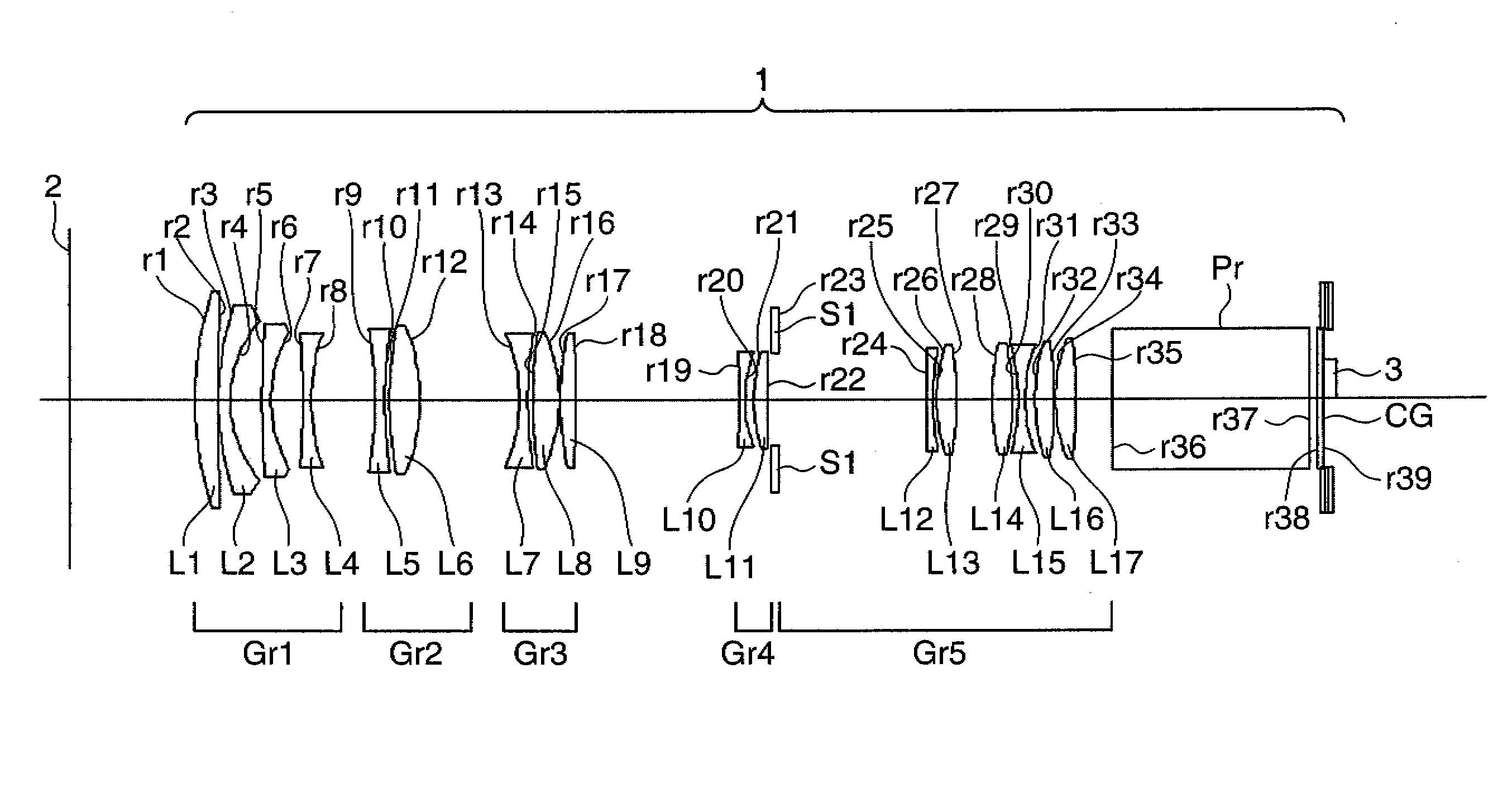
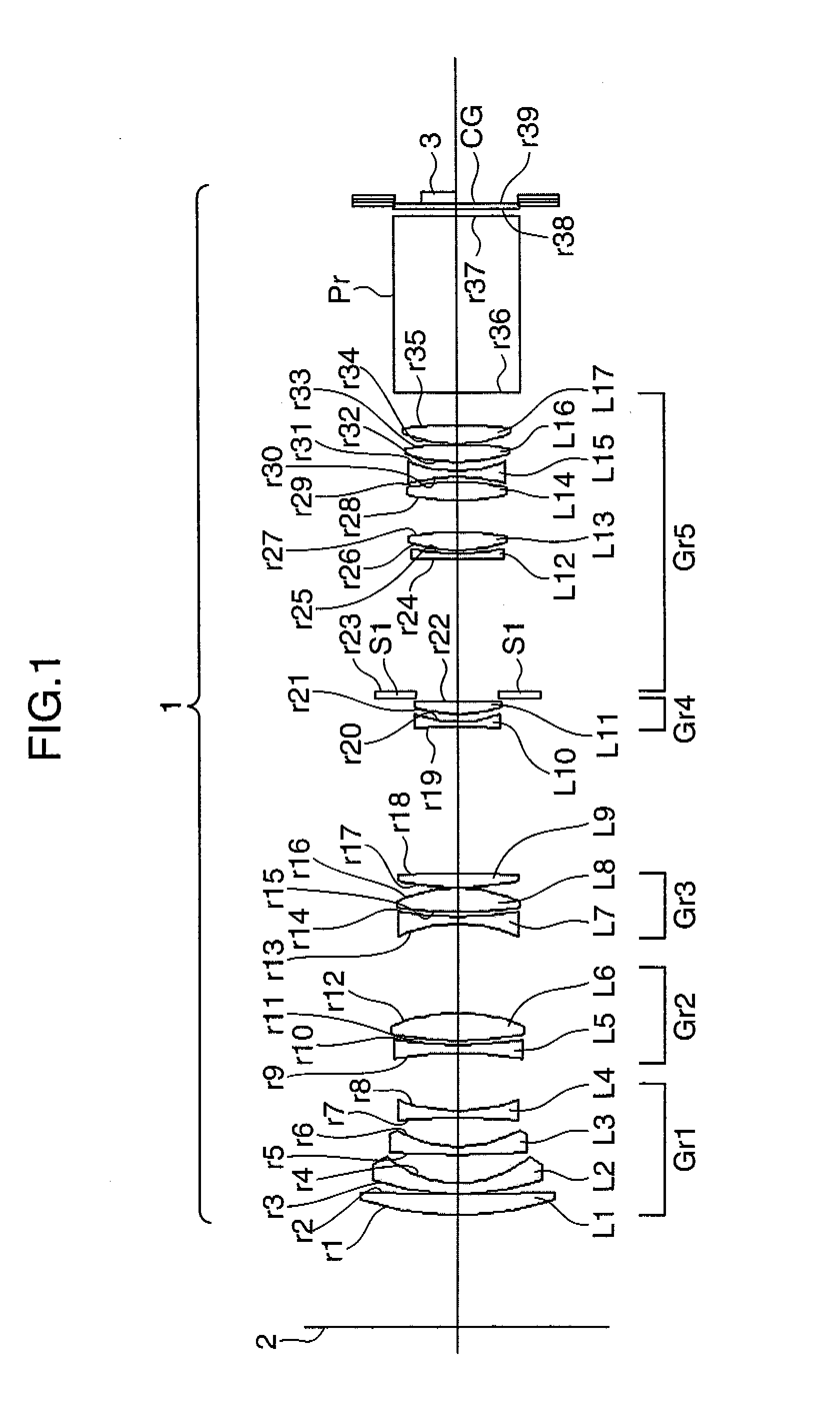
[0048]In this section, described is an example, wherein a projection lens in accordance with the first embodiment of the invention is applied to a projector. FIG. 24 is a diagram showing the entire arrangement of a projector in accordance with the first embodiment. FIG. 1 is a lens arrangement diagram of a projection lens in accordance with the first embodiment.

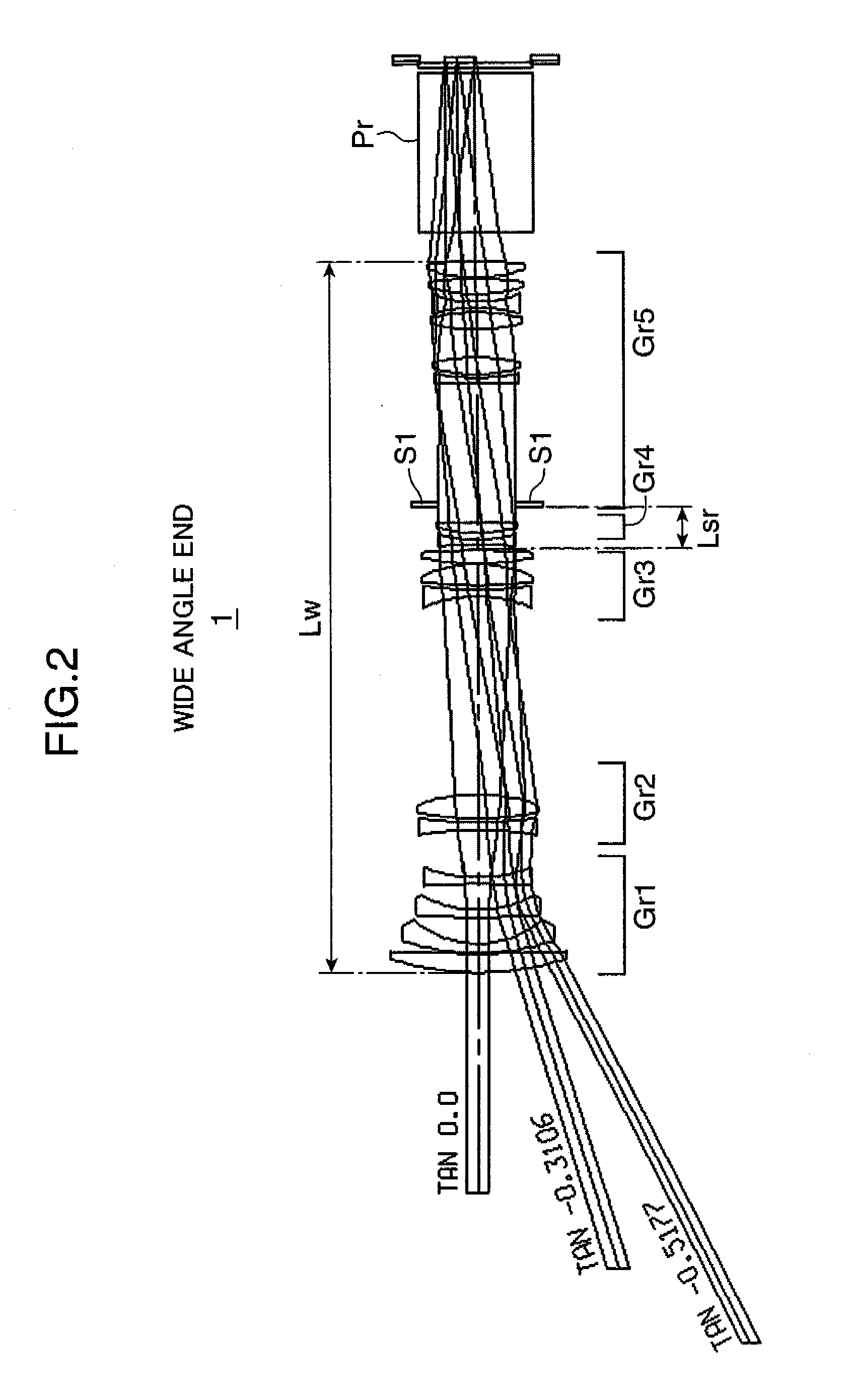
[0049]FIG. 2 is an optical path diagram of the projection lens at a wide-angle end. FIG. 3 is an optical path diagram of the projection lens in a middle focal length position between the wide-angle end and a telephoto end. FIG. 4 is an optical path diagram of the projection lens at the telephoto end.

[0050]As shown in FIG. 24, the projector includes a screen 2, an image generator 3 for generating an image by modulating light, a projection lens 1 for projecting an image onto the screen 2, a light source 4, an illumination optical system 5 for guiding light from the light source 4 to the image generator 3, a prism Pr constituted...

example 1

[0078]In this section, Example 1 of the projection lens 1 in accordance with the first embodiment is described. Construction data of lens elements in Example 1 is as follows. CR indicates a curvature radius of a lens surface of each lens element. T indicates a distance (on-axis distance between lens surfaces) between lens surfaces on the optical axis in an infinite focus position. Nd indicates a refractive index of each lens element with respect to d-line. Vd indicates the Abbe number of each lens element with respect to d-line. The lens surface attached with the symbol ri (i=1, 2, 3, . . . ) indicates the i-th lens surface from the enlargement side.

unit: mmlens surface numberCRTNdVd 1159.12010.1011.516864.2 21150.4570.300 3129.8895.0001.4874970.44 454.18113.898 5408.2304.0991.6229958.12 660.31813.793 7−388.5643.7241.6031160.69 885.750variable 9−163.2774.0001.6200436.2910203.0282.17211167.91013.2351.71353.9412−84.834variable13−74.1253.7521.5317248.8414210.0042.28815254.43511.3171.48...

second embodiment

[0082]FIG. 10 is a lens arrangement diagram of a projection lens 1 in accordance with the second embodiment of the invention. Description on elements in the second embodiment substantially identical or equivalent to those in the first embodiment is omitted herein. As shown in FIG. 10, the projection lens 1 for use in a projector is constituted of a first lens group Gr1 having a negative power, a second lens group Gr2 having a positive power, a third lens group Gr3 having a negative power, and a fourth lens group Gr4 having a positive power. The second and the third lens groups Gr2 and Gr3 serve as movable lens groups, and the second lens group Gr2 serves as a movable lens group having a maximum moving amount.

[0083]The first lens group Gr1 is constituted of lens elements L1 through L6. The second lens group Gr2 is constituted of lens elements L7 through L9. The third lens group Gr3 is constituted of lens elements L10 and L11. The fourth lens group Gr4 is constituted of lens elements ...


PUM


Abstract

An object of the invention is to provide a projection lens capable of sufficiently correcting lateral chromatic aberration at both of the wide-angle end and the telephoto end, with an increased zoom ratio, a less number of lens elements, and less variation in telecentricity.

Description

[0001]This application is based on Japanese Patent Application No. 2008-169197 filed on Jun. 27, 2008, the contents of which are hereby incorporated by reference.BACKGROUND OF THE INVENTION AND RELATED ART STATEMENT[0002]1. Field of the Invention[0003]The present invention relates to a projection lens for use in e.g. a projector having a zoom function, and more particularly to a projection lens for enlarging and projecting an image generated by e.g. a liquid crystal panel or a digital micromirror device onto a screen.[0004]2. Description of the Related Art[0005]There is widely known use of a glass material having an anomalous dispersion characteristic for correcting lateral chromatic aberration of a lens. Unlike a general glass material, the glass material having an anomalous dispersion characteristic has a feature that a graph representing a relation between a partial dispersion ratio and the Abbe number is greatly displaced from a straight line.[0006]The partial dispersion ratio P...

Claims


Application Information

Patent Timeline
Patent Type & Authority Applications(United States)
IPC IPC(8): G02B15/177
CPCG02B15/177G02B13/16G02B15/144511G02B15/145523G02B15/1465
Inventor MASUI, ATSUO
Owner KONICA MINOLTA OPTO
Why Eureka
Try Eureka