Image processing apparatus and method for obtaining position and orientation of imaging apparatus

a technology of image processing apparatus and position and orientation, which is applied in the direction of image analysis, image enhancement, instruments, etc., can solve the problems of inconvenient method, measurement accuracy may not be obtained as expected, and not be suitable for estimating camera position/orientation, etc., to achieve efficient obtaining a position and an orientation of an imaging apparatus

Inactive Publication Date: 2009-04-30
CANON KK
View PDF24 Cites 188 Cited by
  • Summary
  • Abstract
  • Description
  • Claims
  • Application Information

AI Technical Summary

Benefits of technology

[0035]Exemplary embodiments of the present invention are directed to a technique capable of efficiently obtaining a position and an orientation of an imaging apparatus.

Problems solved by technology

However, such a method is not useful since handling such a measurement device or a ruler is troublesome for a user and measurement accuracy may not be obtained as expected.
Even if the location information is accurately generated, it may not be suitable for estimating camera position / orientation.
Therefore, the moving object influences an estimation value of the camera position / orientation and causes an error.
Further, if a registered geometric feature has a repetition pattern that is difficult to discriminate (e.g., a blind or a floor design), the geometric feature tends to be erroneously identified.
Accuracy in estimating the camera position / orientation will deteriorate.
If a number of unnecessary geometric features increases, processing speed will decrease.
However, according to the background art 1, if an object moving in a space is automatically extracted and tracked, an appropriate camera moving path may not be generated.
However, if a selected region is once out of a frame image, work efficiency deteriorates because it is necessary to select the region again.
However, a method for removing an unnecessary image feature (which may cause an estimation error) from a frame image is limited to selecting a two-dimensional image feature in a two-dimensional image.
Thus, work efficiency deteriorates.
However, an automatically registered line feature may include erroneous location information due to an accumulated error when it is positioned far from a marker or known information, or when it is erroneously detected in an image capturing operation.
Estimation accuracy deteriorates if the erroneous location information is present.

Method used


Image

  • Image processing apparatus and method for obtaining position and orientation of imaging apparatus
  • Image processing apparatus and method for obtaining position and orientation of imaging apparatus
  • Image processing apparatus and method for obtaining position and orientation of imaging apparatus

Examples


first exemplary embodiment

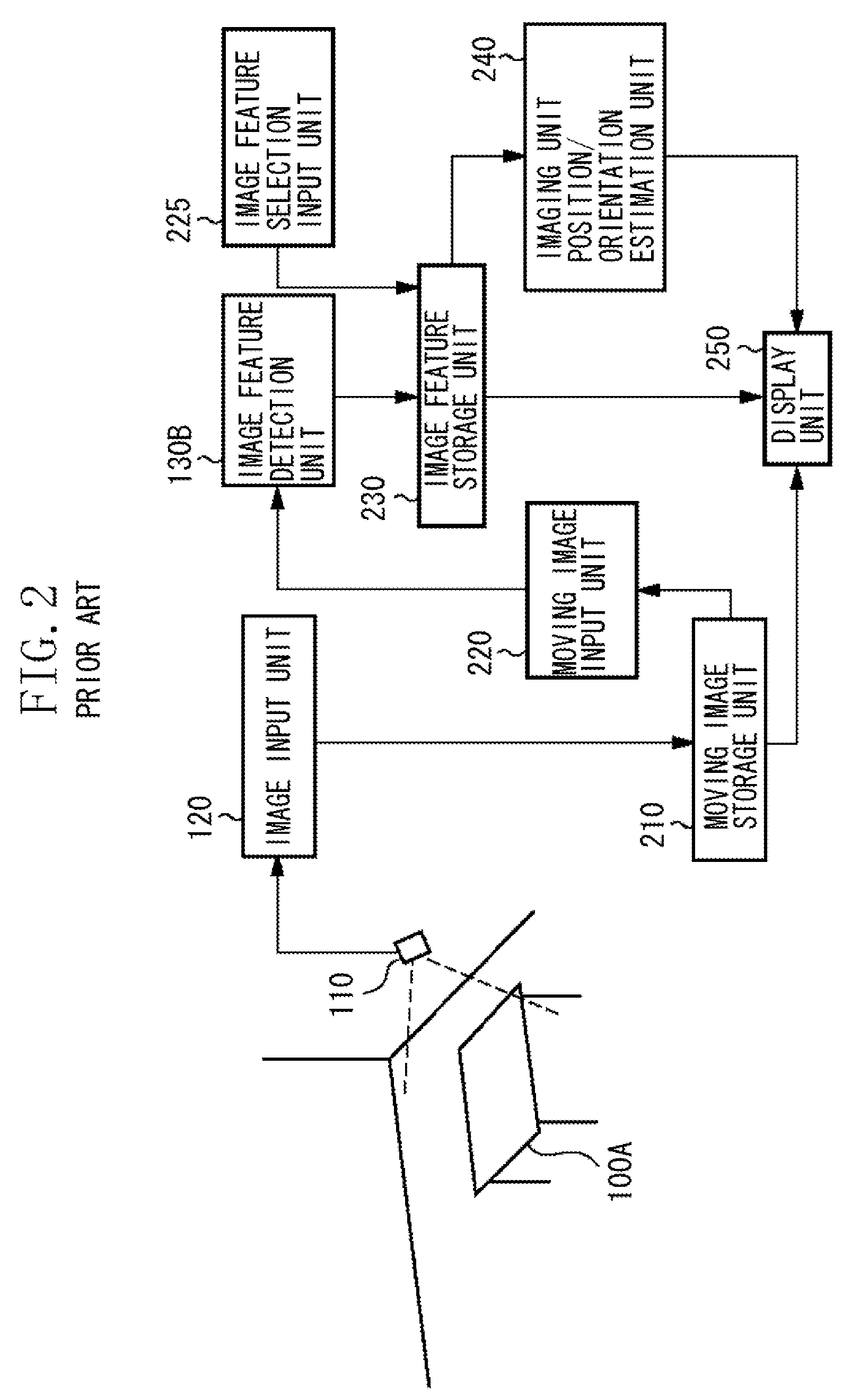
[0059]As described above, when an image feature is selected by designating a 2D region on an image in the match moving technique, the background art 1 has a problem that once a target object is out of a frame of the image, selection processing of the target object needs to be performed again. The background art 2 cannot remove location information which may include an error and cause an identification error. Therefore, estimation accuracy of a camera position / orientation may deteriorate and processing speed may be decreased by processing unnecessary location information.

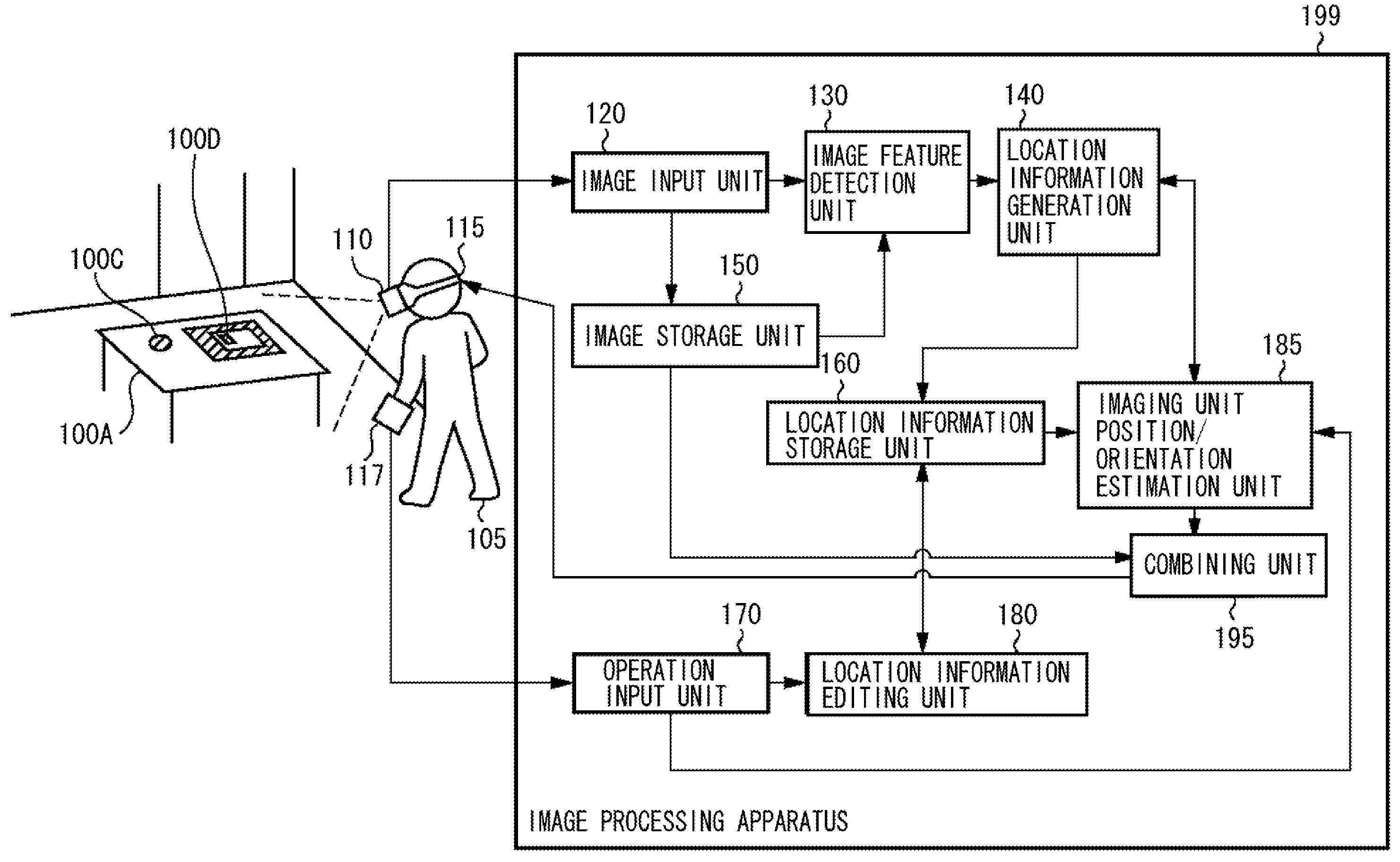
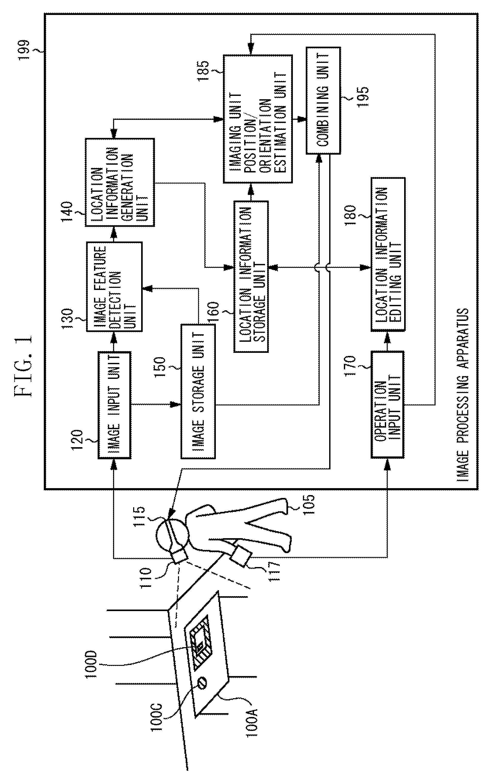
[0060]A first exemplary embodiment of the present invention automatically acquires location information of a geometric feature existing in a physical space based on a captured image entered from a camera. Further, the present exemplary embodiment provides an interface that enables a user to select a geometric feature adequate for estimating a camera position / orientation.

[0061]In the following description, to “select”...

modified embodiment 1

[0206]In the first exemplary embodiment, the imaging unit position / orientation estimation unit 185 sets one of three processing modes (automatic registration processing mode, editing processing mode, and application execution mode). However, a number of processing modes is not limited to three. For example, the automatic registration processing mode and the application execution mode can be integrated into a new application execution mode to reduce the number of processing modes.

[0207]A first modified exemplary embodiment is different from the first exemplary embodiment in the following points. The present modified exemplary embodiment does not include the processing of step S660 illustrated in FIG. 6. More specifically, the present modified exemplary embodiment changes the processing of step S630 and subsequent steps in the main processing that performs a display to notify a user of a geometric feature on a captured image. In the flowchart illustrated in FIG. 7 (i.e., step S630 in ...

modified embodiment 2

[0209]In the first exemplary embodiment, the user 105 wears the HMD 115 on the head. However, when the user 105 holds the camera 110 in his / her hand to capture a physical space, the captured image can be displayed on a monitor of a work station instead of the HMD 115. Any apparatus capable of displaying a result obtained by the HMD 115 is usable. More specifically, a display unit of the HMD 115 can be used as a monitor independently connected to the image processing apparatus 199. The camera 110 can be separated from the HMD 115 so that the user 105 can hold it in his / her hand.


PUM


Abstract

An image processing apparatus obtains location information of each image feature in a captured image based on image coordinates of the image feature in the captured image. The image processing apparatus selects location information usable to calculate a position and an orientation of the imaging apparatus among the obtained location information. The image processing apparatus obtains the position and the orientation of the imaging apparatus based on the selected location information and an image feature corresponding to the selected location information among the image features included in the captured image.

Description

BACKGROUND OF THE INVENTION[0001]1. Field of the Invention[0002]The present invention relates to a technique capable of obtaining position and orientation information of an imaging apparatus based on an image captured by the imaging apparatus.[0003]2. Description of the Related Art[0004]There is a conventional method for measuring a position and an orientation of a physical object in a space which includes capturing an image of the physical object which moves in the space, with a camera and detecting a position of a projection image (referred to as a “image feature”) on an image of a geometric shape or a color feature (referred to as a “geometric feature”). The method further includes capturing the image of the geometric feature in the space and estimating a position and an orientation of the camera in the space. The above-described position / orientation measurement method requires preparing three-dimensional location information of each geometric feature involved in an image (herein...

Claims


Application Information

Patent Timeline
Patent Type & Authority Applications(United States)
IPC IPC(8): G06K9/00G06V10/24
CPCG06K9/32H04N13/207G06T7/73G06V10/24G06T7/60G06T2207/10012G06F18/00
Inventor TAKEMOTO, KAZUKISATOH, KIYOHIDE
Owner CANON KK
Why Eureka
Try Eureka