Portable air compressor

Inactive Publication Date: 2009-04-30
F I A C
View PDF13 Cites 5 Cited by
  • Summary
  • Abstract
  • Description
  • Claims
  • Application Information

AI Technical Summary

Benefits of technology

[0007]The present invention has for an aim to provide a portable air compressor which is free of the above-m

Problems solved by technology

A first disadvantage linked to the use of prior art portable compressors is the fact that they are not very compact and they have many parts directly exposed to knocks and bad weather, despite the fact that sometimes there are guards partly covering some compon

Method used


Image

  • Portable air compressor
  • Portable air compressor
  • Portable air compressor

Examples


Embodiment Construction

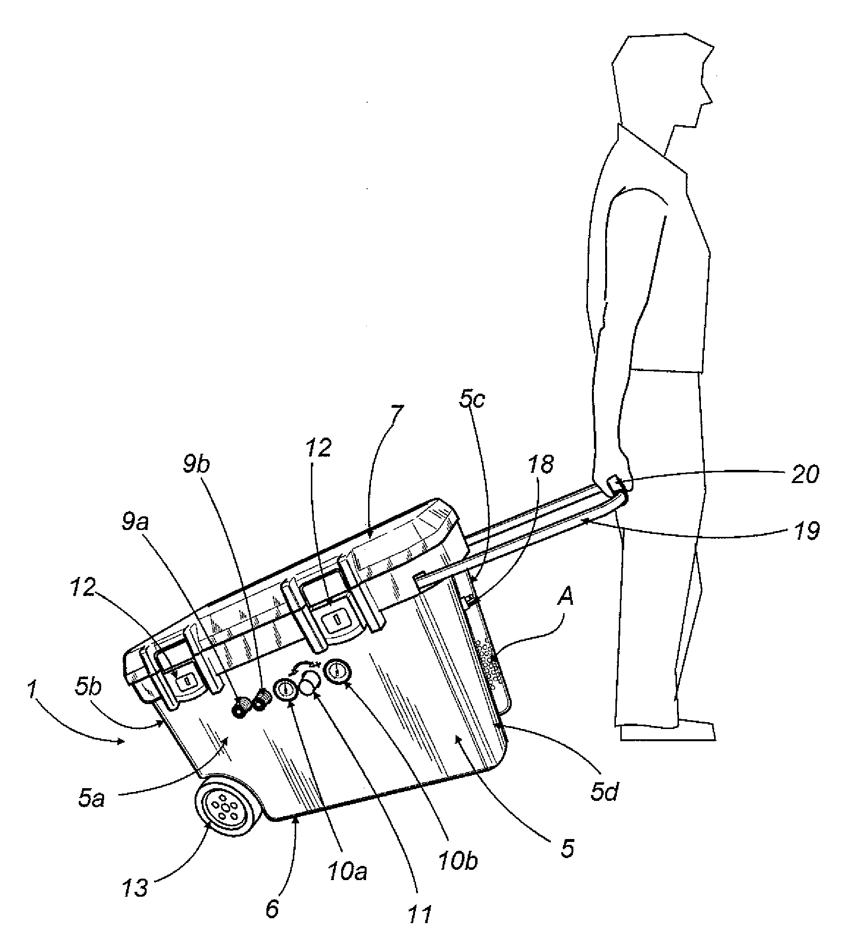
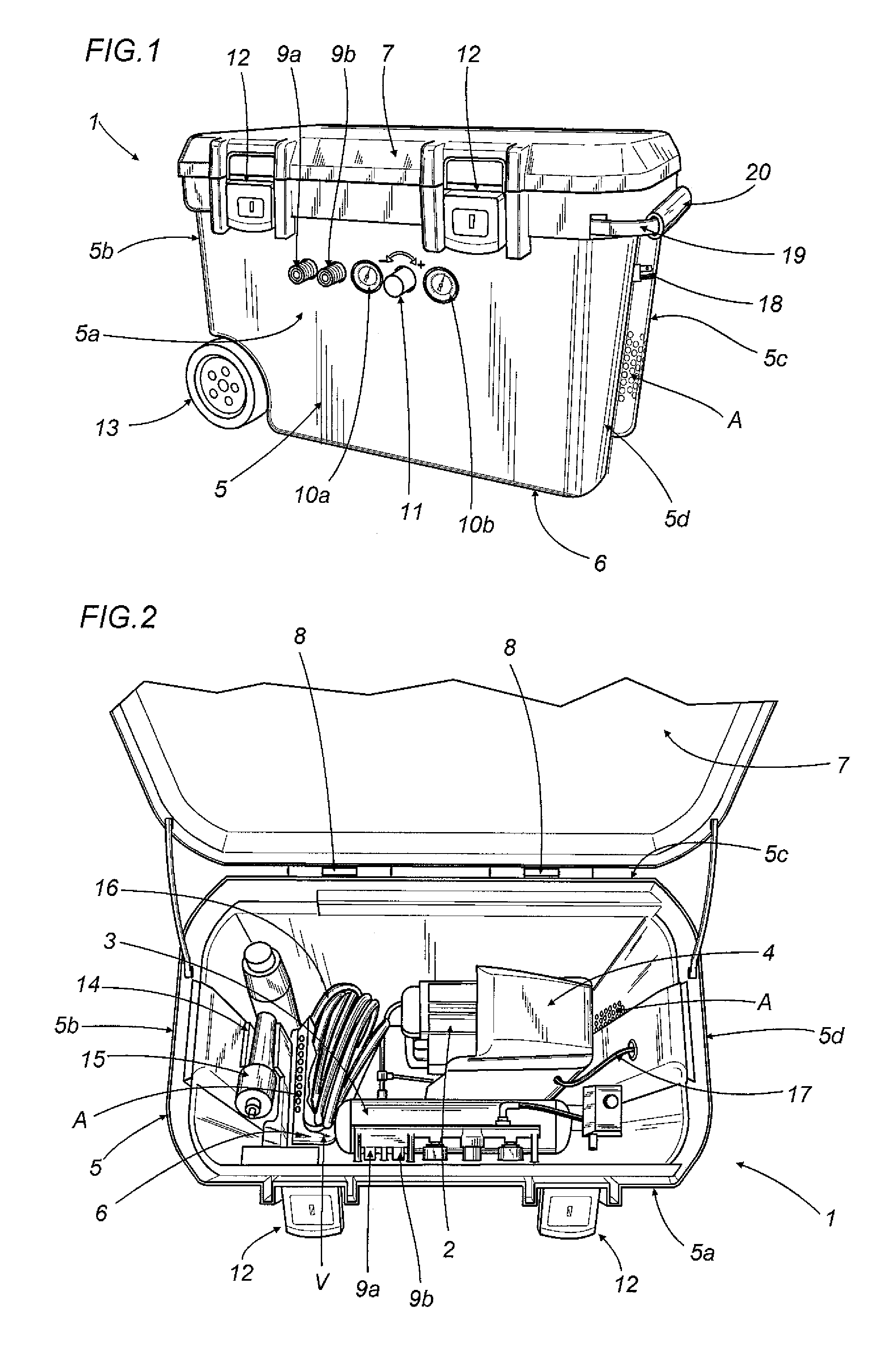
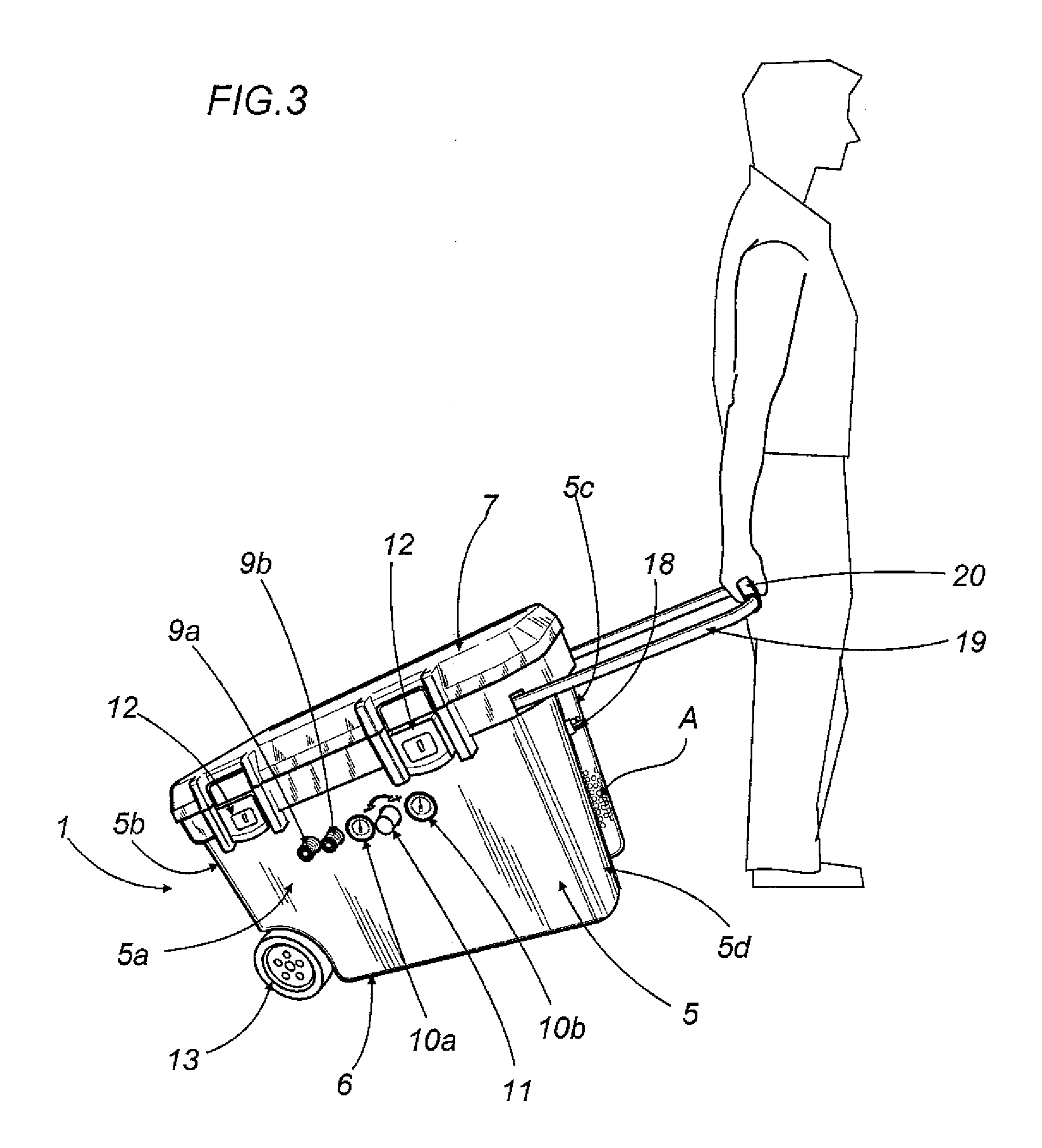
[0013]With reference to the accompanying drawings, the numeral 1 denotes as a whole a portable air compressor in accordance with the present invention.

[0014]With reference to FIG. 2, the compressor 1 comprises an air pumping element 2 and an electric motor which are operatively connected to each other and two compressed air storage tanks 3, only one of which is visible in the accompanying drawings.

[0015]According to the preferred embodiment illustrated, the electric motor is at least partly covered by a guard 4 designed to also convey the air for cooling the motor and the pumping element 2.

[0016]The compressor 1 comprises a cup-type box-shaped container 5, housing the pumping element 2, electric motor and tanks.

[0017]The box-shaped container 5 advantageously has a base 6 having a roughly rectangular shape, four vertical walls 5a, 5b, 5c, 5d extending from the base 6, and a closing lid 7, hinged by suitable hinges 8, on one 5c of the vertical walls.

[0018]As illustrated in FIGS. 1 and...


PUM


Abstract

The portable air compressor (1) comprises an air pumping element (2), an electric motor for driving the pumping element (2), at least one tank (3) for storing the compressed air coming out of the pumping element (2), and a box-shaped container (5) for containing the pumping element (2), the electric motor and the tank (3).

Description

BACKGROUND OF THE INVENTION[0001]The present invention relates to a portable air compressor.[0002]In recent years air compressors, in particular portable ones, have become very widespread and, whilst until not long ago they were used almost exclusively in a few professional limited sectors, today their use is increasingly widespread in the most diverse technical fields, for example construction or yards in general. In many countries, for example in North America or northern Europe, private detached or semi-detached homes are still mostly built from wood and the component parts are advantageously fixed to each other using nails fired from suitable guns powered with compressed air.[0003]Therefore, the use of compressors in construction sites, both for buildings and ships or even other locations, first requires that the compressor and its accessories are easily transportable.[0004]Thus, over the years many types of portable compressors have been made, which definitely proved effective ...

Claims


Application Information

Patent Timeline
IPC IPC(8): F04B53/00F04B17/03
CPCF04B41/02F04B35/06
Inventor LUCCHI, FABIO
Owner F I A C
Why Eureka
Try Eureka