Series fan and frame set thereof

Inactive Publication Date: 2009-04-30
DELTA ELECTRONICS INC
View PDF5 Cites 16 Cited by
  • Summary
  • Abstract
  • Description
  • Claims
  • Application Information

AI Technical Summary

Benefits of technology

[0015]In summary, each frame of the series fan and a frame set thereof of the present invention has at least one locking portion. The frames are connected in series via the locking portion. Compared with prior art, the present invention, without extra components, provides combined frames. Fu

Problems solved by technology

However, such extra components result in a more complicated assembly process, increased labor and inc

Method used


Image

  • Series fan and frame set thereof
  • Series fan and frame set thereof
  • Series fan and frame set thereof

Examples


Example

[0024]The present invention can be more fully understood by reading the subsequent detailed description and examples with references made to the accompanying drawings.

DETAILED DESCRIPTION OF THE INVENTION

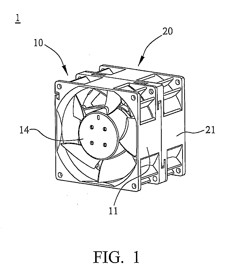
[0025]Referring to FIG. 1, FIG. 1 is a schematic view of an embodiment of a series fan of the present invention. The series fan has a first fan 10 and a second fan 20. The first fan 10 has a first frame 11 and a first impeller 14. The second fan 20 has a second frame 21 and a second impeller (not shown). The first fan 10 and the second fan 20 are connected in series to drive airflow.

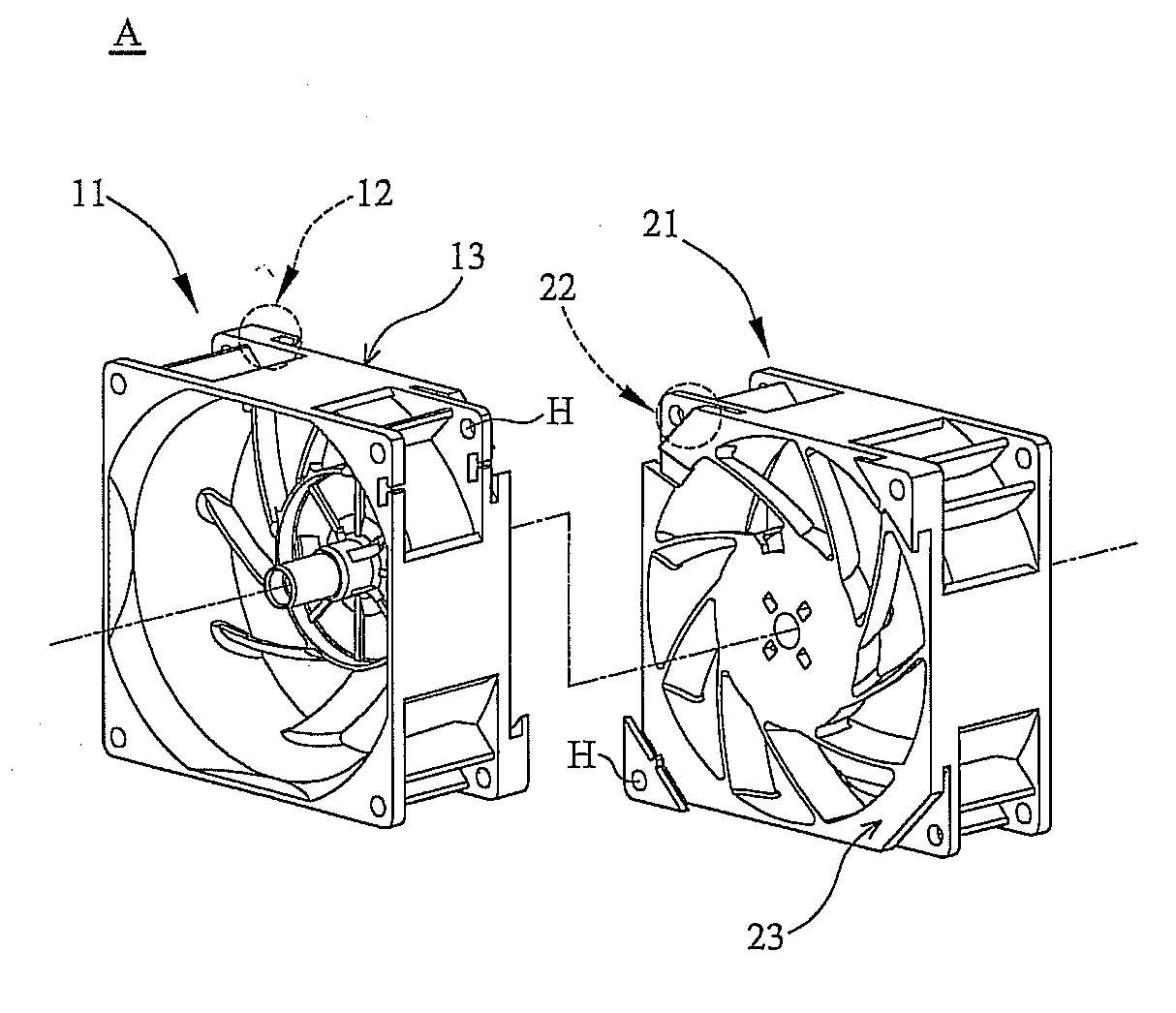
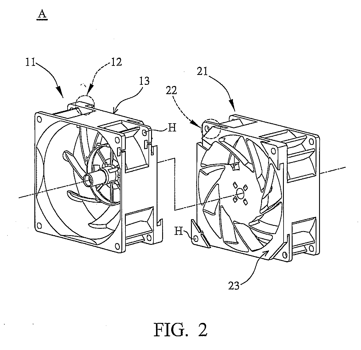
[0026]Simultaneously referring to FIGS. 1 and 2, FIG. 2 is a schematic view of the frame set in FIG. 1. The first frame 11 and the second frame 21 form a frame set A. The first frame 11 has at least one first locking portion 12. The second frame 21 has at least one second locking portion 22. The first locking portion 12 is disposed on the bottom 13 of the first frame 11. The second locking portion 22 cor...


PUM


Abstract

A serial fan is provided and includes a first fan and a second fan. The first fan includes a first frame, and the second fan includes a second frame. The first frame and the second frame form a frame set. The first frame has at least one first locking portion. The second frame has at least one second locking portion disposed corresponding to the first locking portion. When the first fan and the second fan are assembled, the first locking portion inserts in the second locking portion along a rotational direction so that the first frame and the second frame are connected in series.

Description

BACKGROUND OF THE INVENTION[0001]The Non-provisional application claims priority under U.S.C §119(a) on Patent Application No(s). 096218067, field in Taiwan, Republic of China on Oct. 26, 2007, the entire contents of which are hereby incorporated by reference.[0002]1. Field of the Invention[0003]The present invention relates to a series fan and a frame set thereof.[0004]2. Description of the Related Art[0005]As electronic products advance toward higher performance, higher frequency, higher velocity and portability, the heats thereof generate to affect reliability and lifespan. Thus, heat dissipation is important for electronic products. Conventionally, a fan is installed as a heat-dissipating device, and in order to increase heat-dissipating effect, several fans are connected together.[0006]In order to connect at least two fans in series, a conventional method is using screws, rivets, or bolts, to combine the frames of the fans. However, such extra components result in a more compli...

Claims


Application Information

Patent Timeline
IPC IPC(8): F24F9/00
CPCF04D19/007F04D29/646F04D25/0613
Inventor HSU, SHUO-SHIULEE, CHIN-HONG
Owner DELTA ELECTRONICS INC
Why Eureka
Try Eureka