Radiofrequency ablation device

a radio frequency electrosurgical and ablation device technology, applied in the field of radio frequency electrosurgical probes or ablation devices, can solve the problems of cancerous or malignant tissue necrosis, cell death and necrosis, and tissue popping during the application of rf energy to the tissue can be painful for the subj

Active Publication Date: 2009-04-30
BOSTON SCI SCIMED INC
View PDF9 Cites 11 Cited by
  • Summary
  • Abstract
  • Description
  • Claims
  • Application Information

AI Technical Summary

Problems solved by technology

After deployment, RF energy may be transmitted from the electrode tine array to ablate the target tissue, causing heating and eventual necrosis of cancerous or malignant tissue.
Ionic agitation occurs around an active electrode as a result of frictional heating in the tissue surrounding the electrode tines (e.g., electrodes, RF needle probes, and the like) on an array, leading to cell death and necrosis.
The popping of tissue during the application of RF energy to the tissue can be painful to the subject.
The popping sound may also be heard by the patient, thereby raising anxiety and discomfort during the procedure.

Method used


Image

  • Radiofrequency ablation device
  • Radiofrequency ablation device
  • Radiofrequency ablation device

Examples


Embodiment Construction

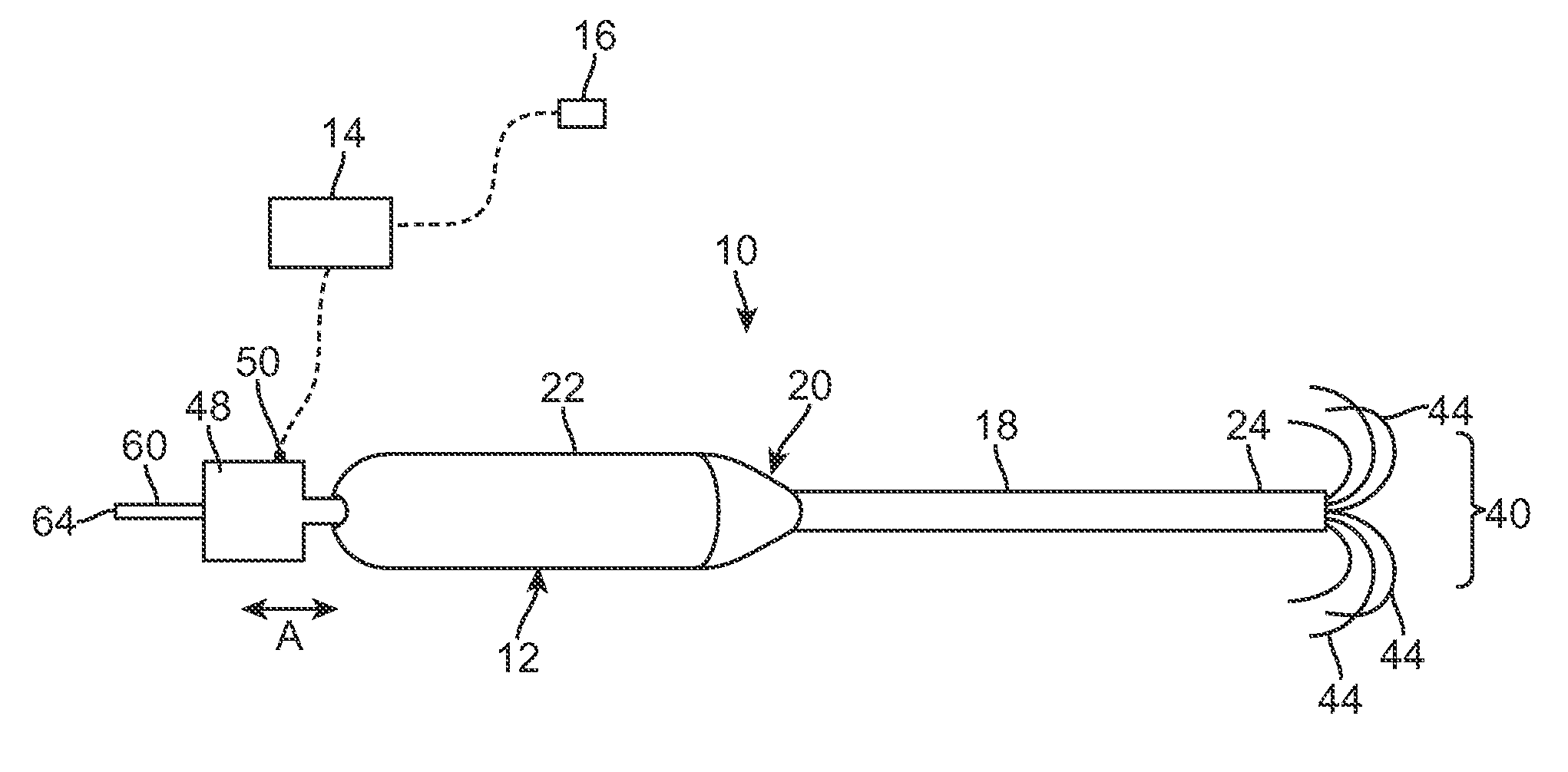
[0026]FIG. 1 illustrates a radiofrequency (RF) ablation device 10 according to one embodiment of the invention. As seen in FIG. 1, the RF ablation device 10 includes probe assembly 12 that is configured for introduction into a body of a patient for ablative treatment of target tissue. The target tissue may include, for example, diseased or cancerous tissue located within an organ or body tissue. As one illustrative example, the RF ablation device 10 may be used to ablate cancerous tissue located within liver tissue although the invention is not limited to the type of tissue being ablated. The RF ablation device 10 is coupled to a RF generator 14 configured for supplying RF energy to the probe assembly 12 in a controlled manner.

[0027]The RF generator 14 typically uses impedance-based feedback designed to accurately monitor the extent and nature of tissue desiccation to accommodate lesion and patient variability. The RF generator 14 is also coupled to an electrode pad 16 as illustrate...


PUM


Abstract

A radiofrequency ablation device includes an elongate cannula having a distal portion and a proximal portion and a lumen extending between the distal and proximal portions. The RF ablation device further includes an elongate tubular member disposed within the lumen of the elongate cannula, the elongate tubular member having a distal region and a proximal region, the elongate tubular member including a lumen extending between the distal and proximal portions. A sildable electrode member is disposed in the portion of the elongate cannula lumen located external to the elongate tubular member. As an alternative to the elongate tubular member, the electrode member may include a lumen. The lumen of the elongate tubular member (or electrode member) carries or vents gaseous vapor generated during the RF ablation process.

Description

RELATED APPLICATION [0001]This Application claims priority to U.S. Provisional Patent Application No. 60 / 983,914 filed on Oct. 30, 2007. The above-noted Application is incorporated by reference as if set forth fully herein.FIELD OF THE INVENTION [0002]The field of the invention generally relates to the structure and use of radio frequency (RF) electrosurgical probes or ablation devices for the treatment of tissue.BACKGROUND OF THE INVENTION [0003]In the field of oncology, cancer treatment is often performed using radio frequency (RF) ablation techniques. Conventional ablation techniques use an array of RF needles or tines (sometimes referred to as a “tine array”), which may be configured to deploy in a pre-determined shape or pattern for transferring RF energy into surrounding tissue. The needles or tines act as electrodes which are electrically connected to a RF generator. The needles or tines thus transmit RF energy into the surrounding tissue for the thermal coagulation and / or ne...

Claims


Application Information

Patent Timeline
Patent Type & Authority Applications(United States)
IPC IPC(8): A61B18/18
CPCA61B18/1477A61B18/148A61B2018/1425A61B2218/008A61B2018/1432A61B2018/1475A61B2018/143
Inventor YOUNG, KIMBOLT
Owner BOSTON SCI SCIMED INC
Why Eureka
Try Eureka