
Software Fault Detection Using Progress Tracker

a technology of software fault and progress tracker, applied in the field of software fault detection, can solve problems such as software failures that cannot be counted

Inactive Publication Date: 2009-04-30
HEWLETT-PACKARD ENTERPRISE DEV LP
View PDF15 Cites 8 Cited by
  • Summary
  • Abstract
  • Description
  • Claims
  • Application Information

AI Technical Summary

Problems solved by technology

Since failed software cannot be counted on to positively indicate its own fault, some fault detection schemes employ a “watchdog” timer.

Method used


Image

  • Software Fault Detection Using Progress Tracker
  • Software Fault Detection Using Progress Tracker

Examples


Embodiment Construction

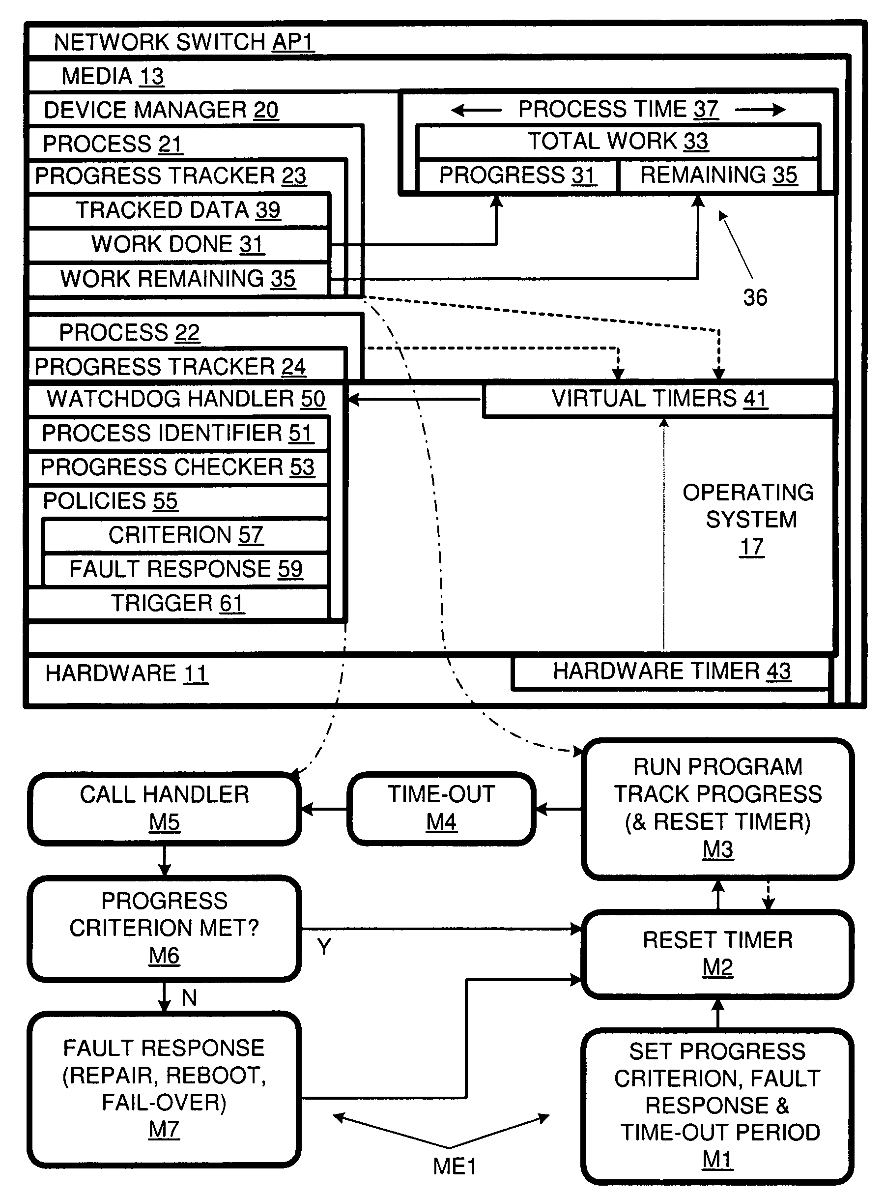
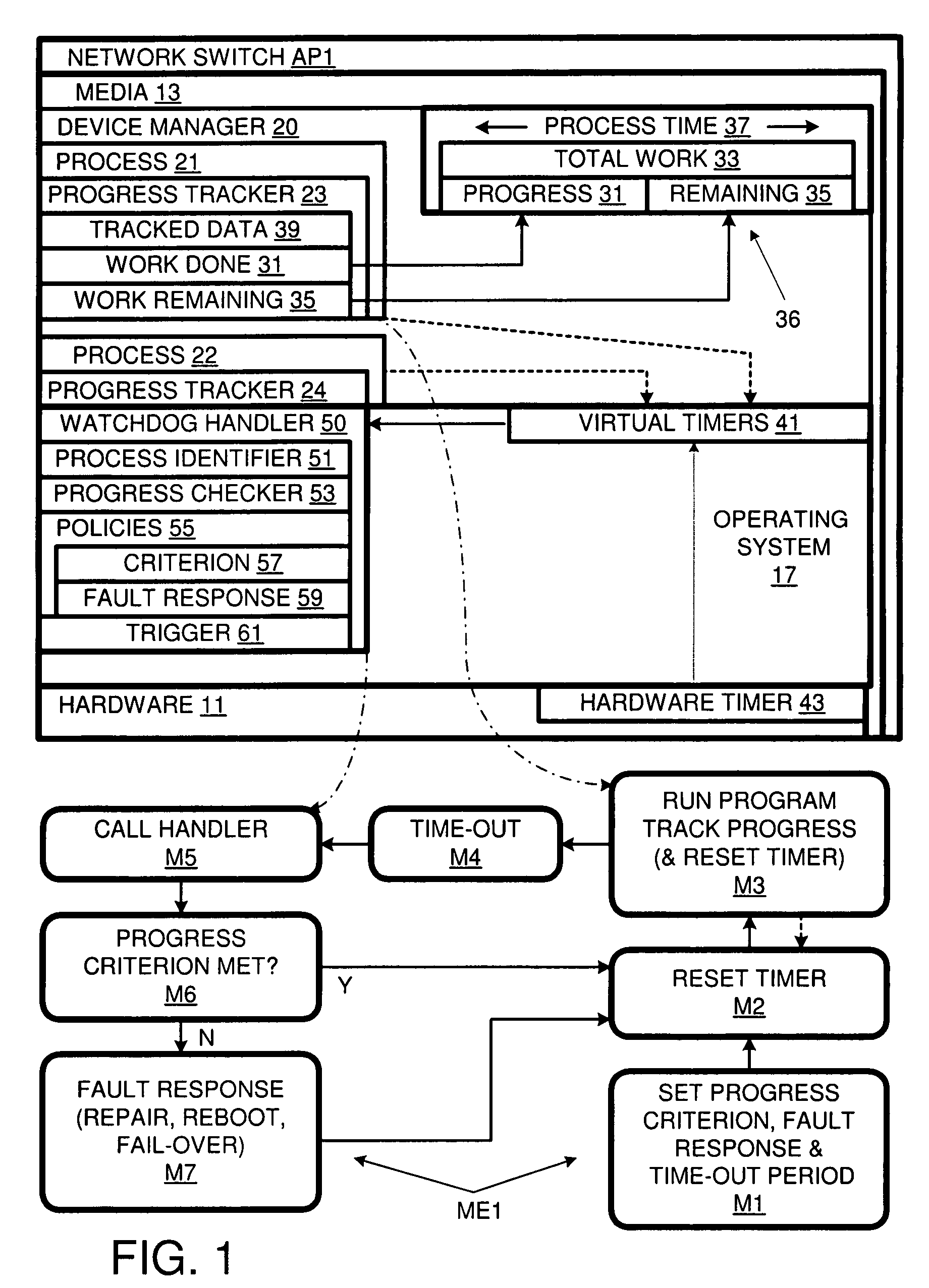
[0007]In accordance with an embodiment of the present invention, the response to a process time-out is a determination of whether or not a fault has occurred (rather than a direct fault response). A process tracks its own progress; upon a time-out, a handler checks the progress. Only if the progress fails to meet a progress criterion (or meets a fault criterion) is a fault response is executed. Otherwise, the process is allowed to continue. Accordingly, the time-out period can be set to meet the time requires for fault detection and independently of the time required for the process to complete a task. Thus, the tradeoff involved in the conventional watchdog approach is avoided.

[0008]A network switch AP1 in accordance with an embodiment of the invention is shown in FIG. 1. Network node devices, such as computers and printers may rely on network switch AP1 for their communications. Accordingly, down time for switch AP1 can be costly in terms of overall network functionality.

[0009]Net...


PUM


Abstract

The invention provides for software fault detection. A software process tracks its own progress. In the event the timer times out, a handler checks the progress. If the progress meets a fault criterion, a fault response is executed.

Description

BACKGROUND OF THE INVENTION[0001]The present invention relates to software fault detection. Many network devices rely on continuously running software for proper operation. When a software fault occurs some corrective action must be taken, e.g., a reboot or fail-over to another instance of the software. Before the corrective action is taken, the fault must be detected.[0002]Since failed software cannot be counted on to positively indicate its own fault, some fault detection schemes employ a “watchdog” timer. This can be a hardware timer or a virtual timer provided by an operating system based on a hardware timer. A watchdog timer counts (up or down) to some threshold at which it will trigger an interrupt or other fault response. The software being “watched” is designed to repeatedly reset the watchdog timer so that it does not time out as long as the software is functioning properly.[0003]Setting the time-out period can involve a tradeoff between: 1) allowing for long-duration actio...

Claims


Application Information

Patent Timeline
IPC IPC(8): G06F11/00
CPCG06F11/0757
Inventor REILLY, JOHN R.
Owner HEWLETT-PACKARD ENTERPRISE DEV LP
Learn More