Washing machine and manufacturing method thereof

a technology of washing machine and manufacturing method, which is applied in the field of washing machines, can solve the problems of deterioration of productivity, damage to the tub, and complicating the assembly process, and achieve the effect of simplifying the assembly process and reducing manufacturing costs

Active Publication Date: 2009-05-07
DAEWOO ELECTRONICS CO LTD
View PDF4 Cites 9 Cited by
  • Summary
  • Abstract
  • Description
  • Claims
  • Application Information

AI Technical Summary

Benefits of technology

[0011]The present invention is conceived to solve the problems of the conventional techniques as described above, and an aspect of the present invention is to provide a washing machine and manufacturing method thereof capable of maintaining concentricity of a stator and simplifying an assembly process to reduce manufacturing costs.

Problems solved by technology

Thus, in the structure of the conventional drum type washing machine wherein the stator is installed to have a radial direction facing the ground, use of a stator having a weight of 1.5 kg or more and fastened to the tub causes many problems such as damage of the tub and the like.
In this case, however, separate processes of coupling the bearing housing and the supporter to the rear wall of the tub are needed, thus complicating an assembly process, which in turn deteriorates productivity.
Further, since this structure requires an increased number of assembling steps, there is a problem in that assembly errors can occur due to such an increased number of assembling steps, thus causing deviation of concentricity of the bearing housing and the stator.

Method used


Image

  • Washing machine and manufacturing method thereof
  • Washing machine and manufacturing method thereof
  • Washing machine and manufacturing method thereof

Examples


first embodiment

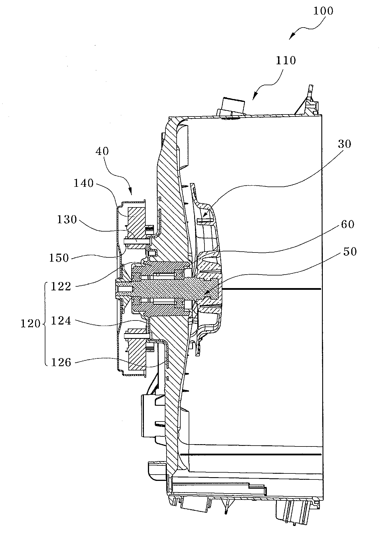
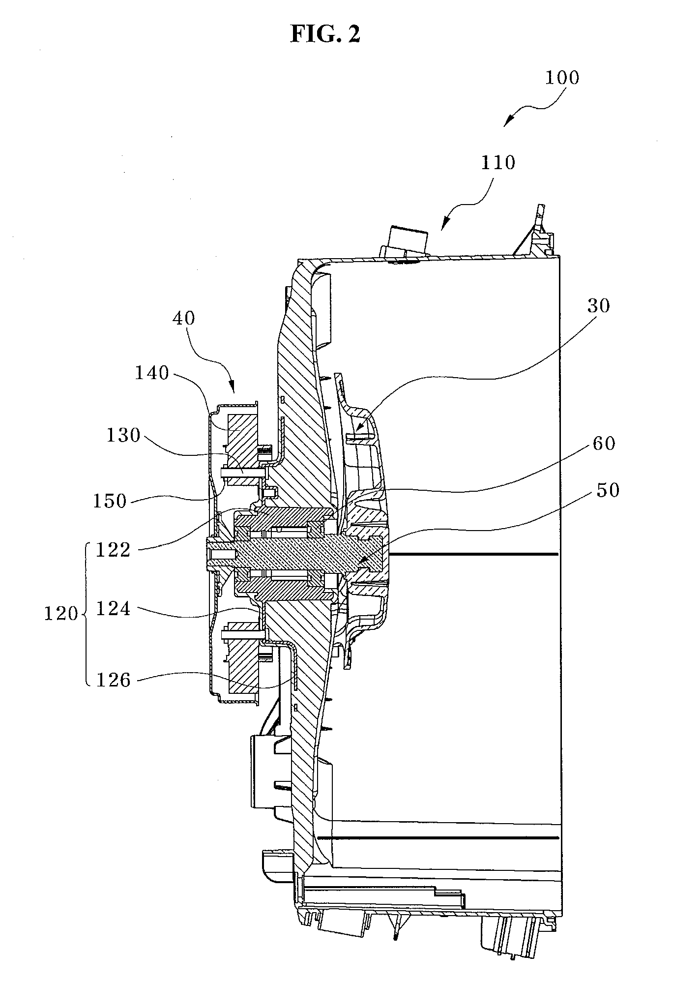
[0037]FIG. 2 is a section side elevation of a washing machine according to the present invention, FIG. 3 is a perspective view of a bearing housing shown in FIG. 2, and FIG. 4 is a perspective view of the bearing housing and a fastening member shown in FIG. 2.

[0038]Referring to FIGS. 2 to 4, the washing machine 100 according to the first embodiment of the present invention includes a tub 110, a bearing housing 120, a fastening member 130, and a stator 140.

[0039]The tub 110 is disposed inside a cabinet (not shown) of the washing machine. The tub 110 is an injection molded product and can be formed of plastics or synthetic resins. The washing machine has a drum 30 rotatably disposed inside the tub 110. A shaft 50 is connected with the drum 30 through the center of a rear wall of the tub 110 to transmit a drive force from a motor 40 to the drum 30.

[0040]The bearing housing 120 supports a bearing 60 that is disposed at either end of the shaft 50.

[0041]The bearing housing 120 is provided...

second embodiment

[0062]Referring to FIG. 6, the washing machine 200 further includes a supporter 260. The supporter 260 is configured to closely support the stator 140 such that the concentricity of the stator 140 can be maintained when fastening the stator 140 so as to closely contact the rear wall of the tub 110.

[0063]Supporting of the supporter 260 with respect to the stator 140 can be accomplished via point contacts at a plurality of points. Alternatively, it can be accomplished via a line contact or surface contact.

[0064]As such, the supporter 260 closely contacts the whole body of the stator 140, thereby preventing deviation of the concentricity due to concentration of a fastening force or supporting force on a particular portion of the stator 140.

[0065]With the stator 140 mounted to the fastening member 130 in Operation S130, the supporter 260 is mounted to the fastening member 130 to be located outside the stator 140 in Operation S240.

[0066]Then, when the nut member 150 is coupled to the fa...

third embodiment

[0067]FIG. 8 is a perspective view of a bearing housing and a fastening member of a washing machine according to the present invention. Herein, the same reference numerals as those of the aforementioned embodiments will denote the same components having the same functions, and a repetitious description thereof will be omitted.

[0068]Unlike the fastening member 130 (see FIG. 4) of the first embodiment, a fastening member 330 of the washing machine according to the third embodiment includes a fastening hole 332 having a thread formed on an inner circumference of the fastening member 330. Accordingly, instead of the nut member 150 (see FIG. 2), the washing machine of this embodiment includes a bolt member 350 having a thread on an outer circumference of the bolt member 350 in order to assemble the stator 140 to the rear wall of the tub 110.

[0069]As apparent from the above description, in the washing machine according to the present invention, a bearing housing is insert-injected to a tu...


PUM

PropertyMeasurementUnit
weightaaaaaaaaaa
circumferenceaaaaaaaaaa
mechanical forceaaaaaaaaaa

Abstract

A washing machine and a method for manufacturing the same are disclosed. The washing machine includes a tub, a bearing housing having a fastening member and formed by insert-injection molding into the tub so as to expose the fastening member from the tub, and a stator mounted to the fastening member. The washing machine can maintain concentricity of the stator and permit simplification of an assembly process to reduce manufacturing costs.

Description

BACKGROUND OF THE INVENTION[0001]1. Field of the Invention[0002]The present invention relates to a washing machine and, more particularly, to a washing machine and manufacturing method thereof capable of simplifying an assembly process and maintaining concentricity of a stator.[0003]2. Description of the Related Art[0004]Generally, a washing machine is designed to wash laundry using a suitable detergent and mechanical force. Particularly, a drum type washing machine is designed to receive the laundry in a horizontally disposed drum which is rotated by a drive force from a motor, and to wash the laundry by impact generated between the laundry and the drum when the laundry is lifted and dropped inside the rotating drum. The drum type washing machine has many advantages, such as effective washing, minimal damage to and less entanglement of laundry, etc.[0005]FIG. 1 is a section side elevation of a conventional drum type washing machine.[0006]Referring to FIG. 1, a conventional drive un...

Claims


Application Information

Patent Timeline
Patent Type & Authority Applications(United States)
IPC IPC(8): D06F37/20B29C45/00
CPCD06F37/269D06F37/262
Inventor HA, DEOK HWAN
Owner DAEWOO ELECTRONICS CO LTD
Why Eureka
Try Eureka