Collision test apparatus and collision test method

a test apparatus and collision technology, applied in the direction of measuring devices, material strength using single impulsive force, instruments, etc., can solve the problems of difficulty in handling the test apparatus and the consequent increase in costs, and achieve the effect of simple and economical structure of the collision test apparatus

Inactive Publication Date: 2009-05-07
HONDA MOTOR CO LTD
View PDF21 Cites 15 Cited by
  • Summary
  • Abstract
  • Description
  • Claims
  • Application Information

AI Technical Summary

Benefits of technology

[0008]The present invention has been made with the foregoing situations taken into consideration. An object of the present invention is to provide a collision test apparatus and a collision test method which are capable of projecting a projectile to a test piece accurately although the structure of the collision test apparatus is simple and economical.

Problems solved by technology

This brings about not only a problem that it is difficult to handle the test apparatus, but also a problem that the facilities have to be large so that the costs are accordingly pushed up.

Method used


Image

  • Collision test apparatus and collision test method
  • Collision test apparatus and collision test method
  • Collision test apparatus and collision test method

Examples


first embodiment

[0038]First of all, descriptions will be provided for the present invention on the basis of FIGS. 1 to 9.

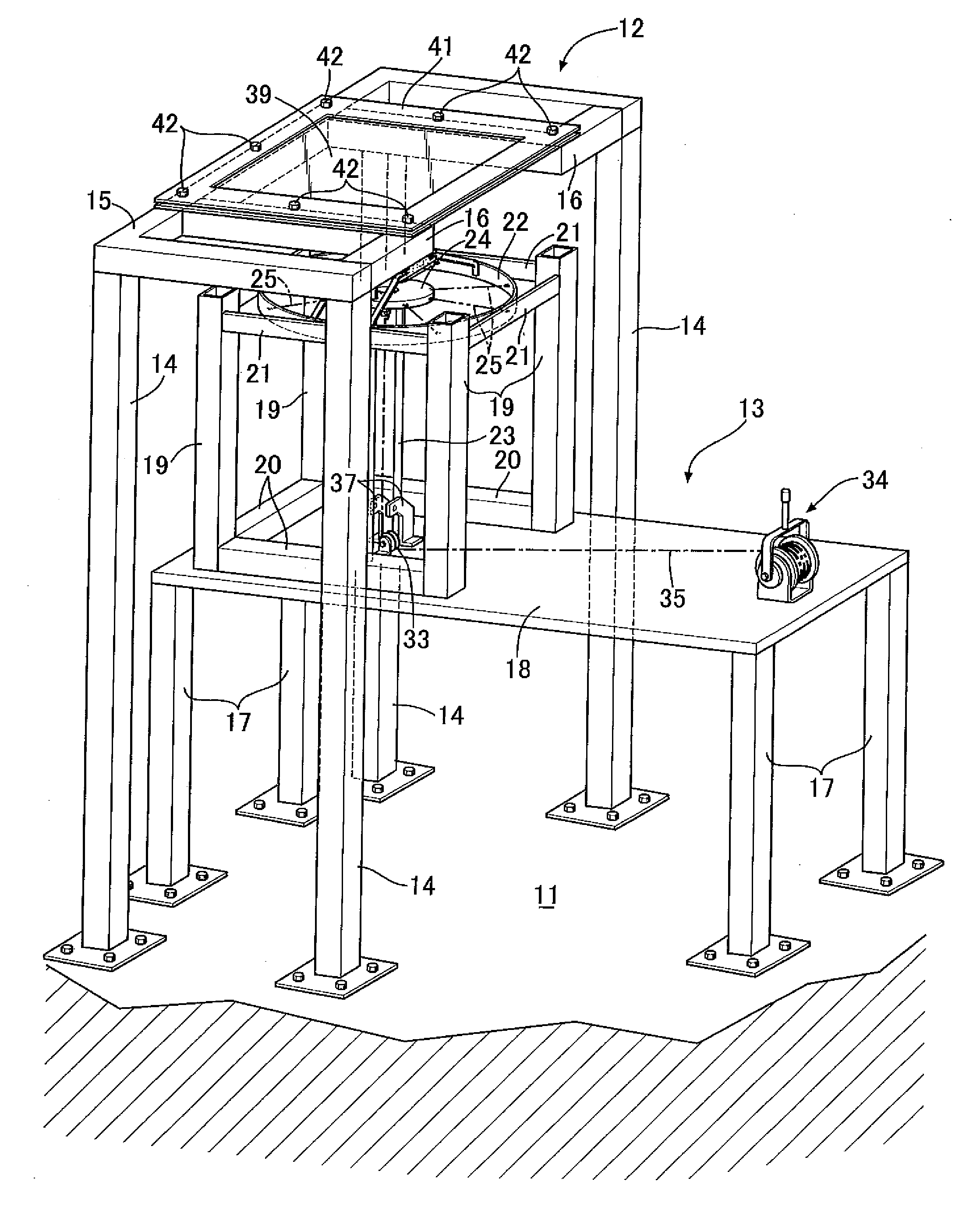
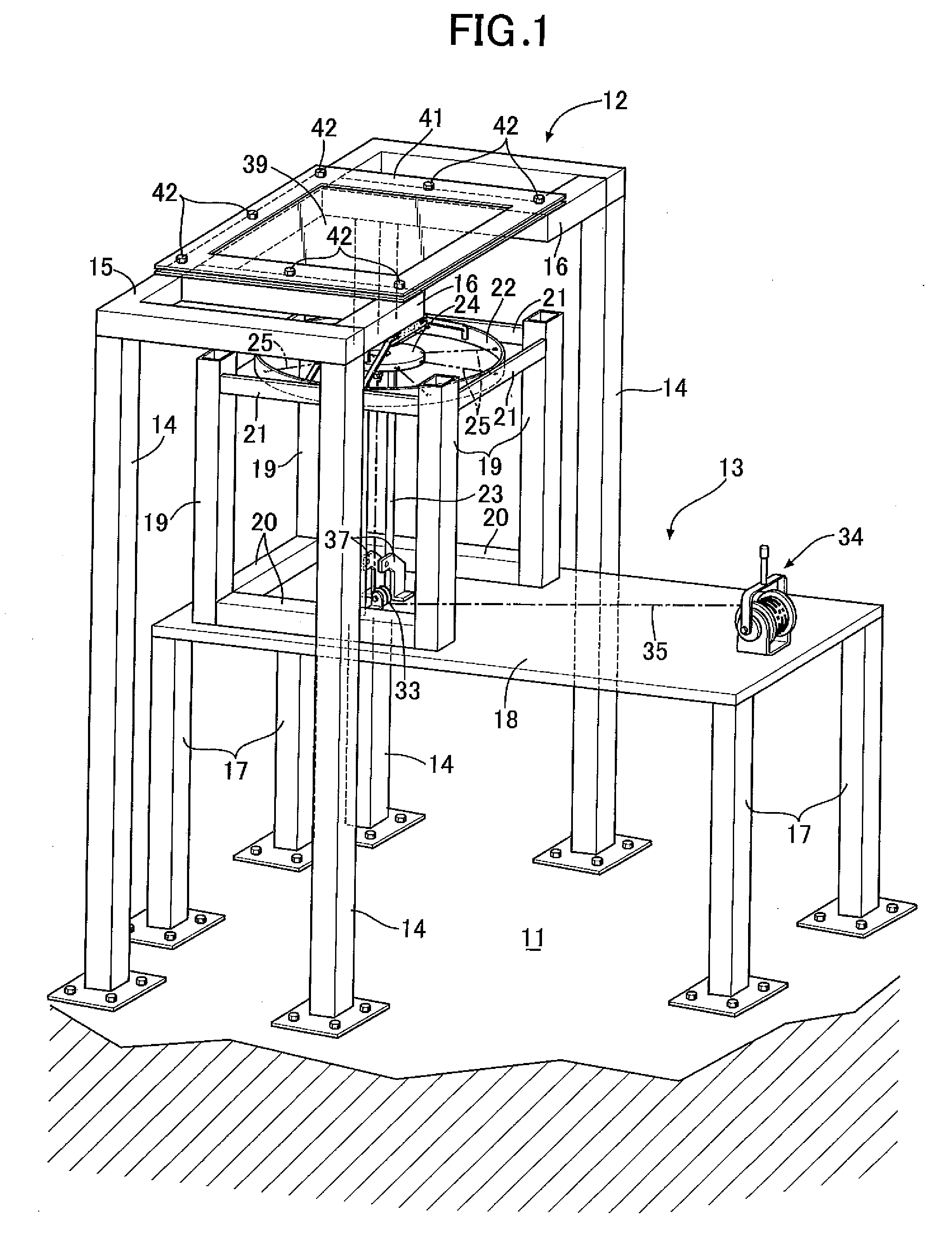
[0039]As shown in FIG. 1, a collision test apparatus supported by a floor 11 is configured of a test piece supporting base 12 and a projection device 13. The test piece supporting base 12 and the projection device 13 are supported by the floor 11 in a way that the test piece supporting base 12 and the projection device 13 are separate from and independent of each other. In other words, the test piece supporting base 12 and the projection device 13 are connected to each other through the floor 11 only, and are connected to each other through nothing but the floor 11.

[0040]The test piece supporting base 12 includes: four columns 14 installed upright on the floor 11; an angular U-shaped beam 15 with which the upper ends of the respective four columns 14 are connected to each other; and two L-shaped frame members 16, 16 connected to the beam 15 in the same plane.

[0041]The projection ...

second embodiment

[0061]Next, descriptions will be provided for the present invention on the basis of FIGS. 10 and 11.

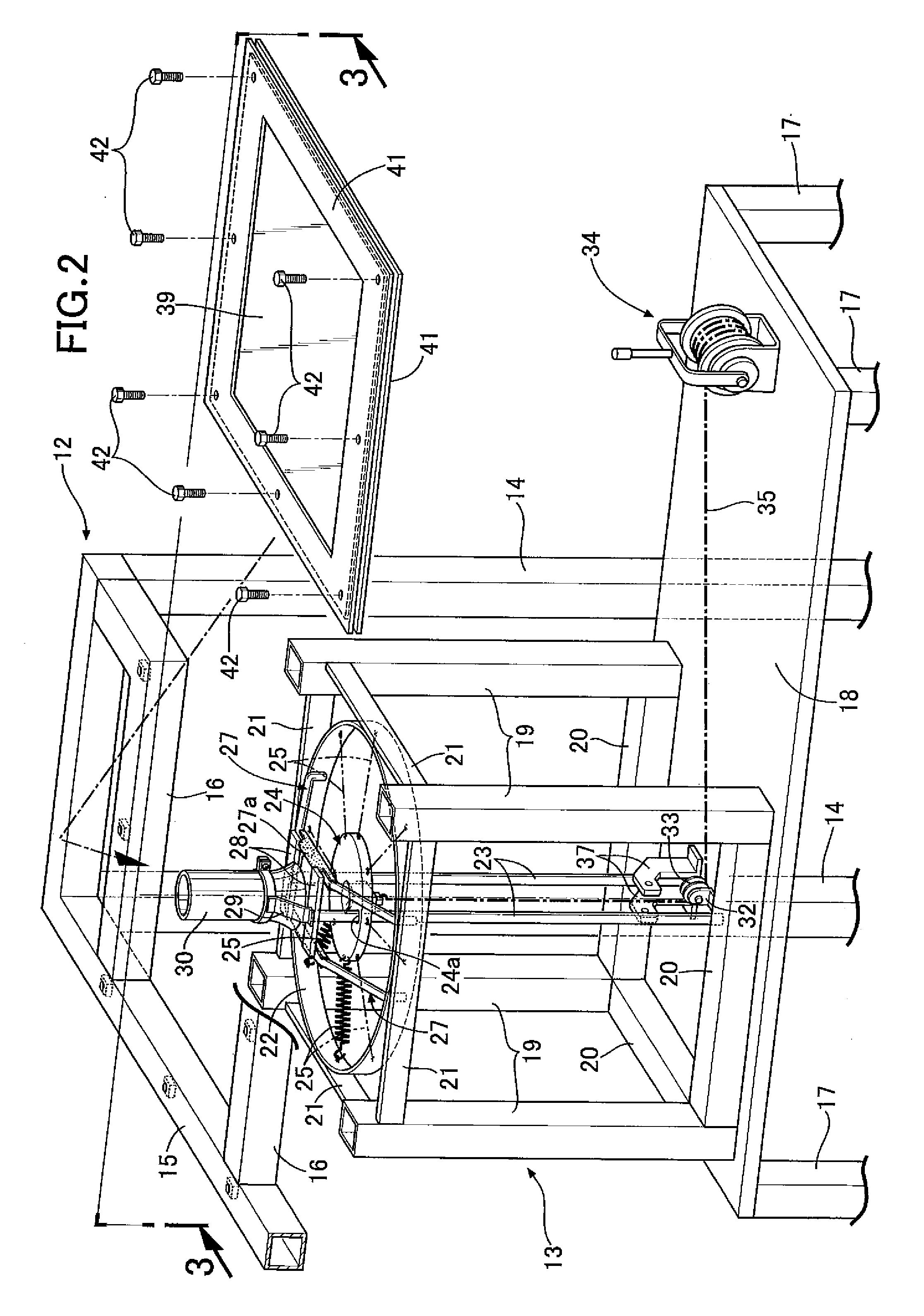
[0062]The collision test apparatus according to the first embodiment (see FIGS. 2 and 3) includes: the two guide rods 23, 23 for guiding the movement of the projectile supporting part 24; and the guide cylinder 30 for guiding the projectile 26 projected toward the test piece 39. By contrast, a collision test apparatus according to a second embodiment includes neither the guide rods 23, 23 nor the guide cylinder 30.

[0063]The collision test apparatus according to the second embodiment is different from the collision test apparatus according to the first embodiment in that the collision test apparatus according to the first embodiment causes the projectile supporting part 24 to be driven by use of the eight coil springs 25, and in that the collision test apparatus according to the second embodiment causes the projectile supporting part 24 to be driven by use of 16 coils sprints 25, which...


PUM

PropertyMeasurementUnit
diameteraaaaaaaaaa
collision speedaaaaaaaaaa
collision speedsaaaaaaaaaa

Abstract

A projection device is configured by connecting a projectile supporting part to a spring supporting frame with multiple coil springs. The projectile supporting part is pulled while deforming the coil springs; a projectile is projected by accelerating the projectile supporting part, supporting the projectile, with restoring forces of the coil springs; and the projectile is collided with a test piece supported by the test piece supporting base. Thereby, it is possible to check a state of collision of the projectile with the test piece or how the test piece is damaged thereby. Since the projectile is projected with the restoring forces of the deformed coil springs, the collision test apparatus is simple and compact in structure, low-cost, and easy-to-handle in comparison with projection of a projectile with compressed air.

Description

BACKGROUND OF THE INVENTION[0001]1. Field of the Invention[0002]The present invention relates to a collision test apparatus and a collision test method which collide a projectile projected from a projection device with a test piece supported by a test piece supporting base for checking a state of collision of the projectile with the test piece or how the test piece is damaged thereby.[0003]2. Description of the Related Art[0004]Japanese Patent Application Laid-open No. 58-195798 has made publicly known an object ejecting apparatus for conducting a strength test by colliding a bird with a windshield glass of an aircraft at a predetermined speed, or colliding an object such as a stone with a construction material at a predetermined speed. The object ejecting apparatus includes a sabot supporting an ejected object at the sabot's front end, the sabot housed movably in a cylinder, and makes the sabot collide with stoppers by accelerating the sabot by use of compressed air reserved in an ...

Claims


Application Information

Patent Timeline
Patent Type & Authority Applications(United States)
IPC IPC(8): G01N3/30
CPCG01N3/30
Inventor KANEKO, AKIRA
Owner HONDA MOTOR CO LTD
Why Eureka
Try Eureka