Biped Mobile Mechanism

a mobile mechanism and bicep technology, applied in the direction of manipulators, program-controlled manipulators, manufacturing tools, etc., can solve the problems of short transition time, short time required for transition, and inability to supply rigidity or rigidity at the toes when running on the wheels. , to achieve the effect of short transition time and high rigidity

Inactive Publication Date: 2009-05-07
HITACHI LTD
View PDF2 Cites 45 Cited by
  • Summary
  • Abstract
  • Description
  • Claims
  • Application Information

AI Technical Summary

Benefits of technology

[0005]An object, according to the present invention, is to provide a robot, for achieving a leg mechanism having high rigidity, so as to enable moving on the wheels, on the leveled ground, and also moving on the bipedalism, on the unleveled ground, and further that mechanism can be switched between the on-wheel running and the bipedalism.
[0010]According to the present invention mentioned above, it is possible to provide a leg mechanism having high rigidity, so as to enable moving on the wheels, on the leveled ground, and also moving on the bipedalism, on the unleveled ground, and further this mechanism provides a robot enabling to execute exchanging between the wheel running and the bipedalism in a short time.

Problems solved by technology

However, with such the method as was mentioned above, because of much degrees of freedom to be passed through, from the wheels up to a trunk, there is a possibility of shortage of stiffness or rigidity at the toes when running on the wheels.
Also, when switching between the running on the wheels and the bipedalism, it is necessary to change the condition of the wheels to touch on the ground, and therefore the time necessary for transition thereof comes to be long.

Method used


Image

  • Biped Mobile Mechanism
  • Biped Mobile Mechanism
  • Biped Mobile Mechanism

Examples


Embodiment Construction

[0021]Hereinafter, an embodiment according to the present invention will be fully explained by referring to FIGS. 1 to 9 attached herewith.

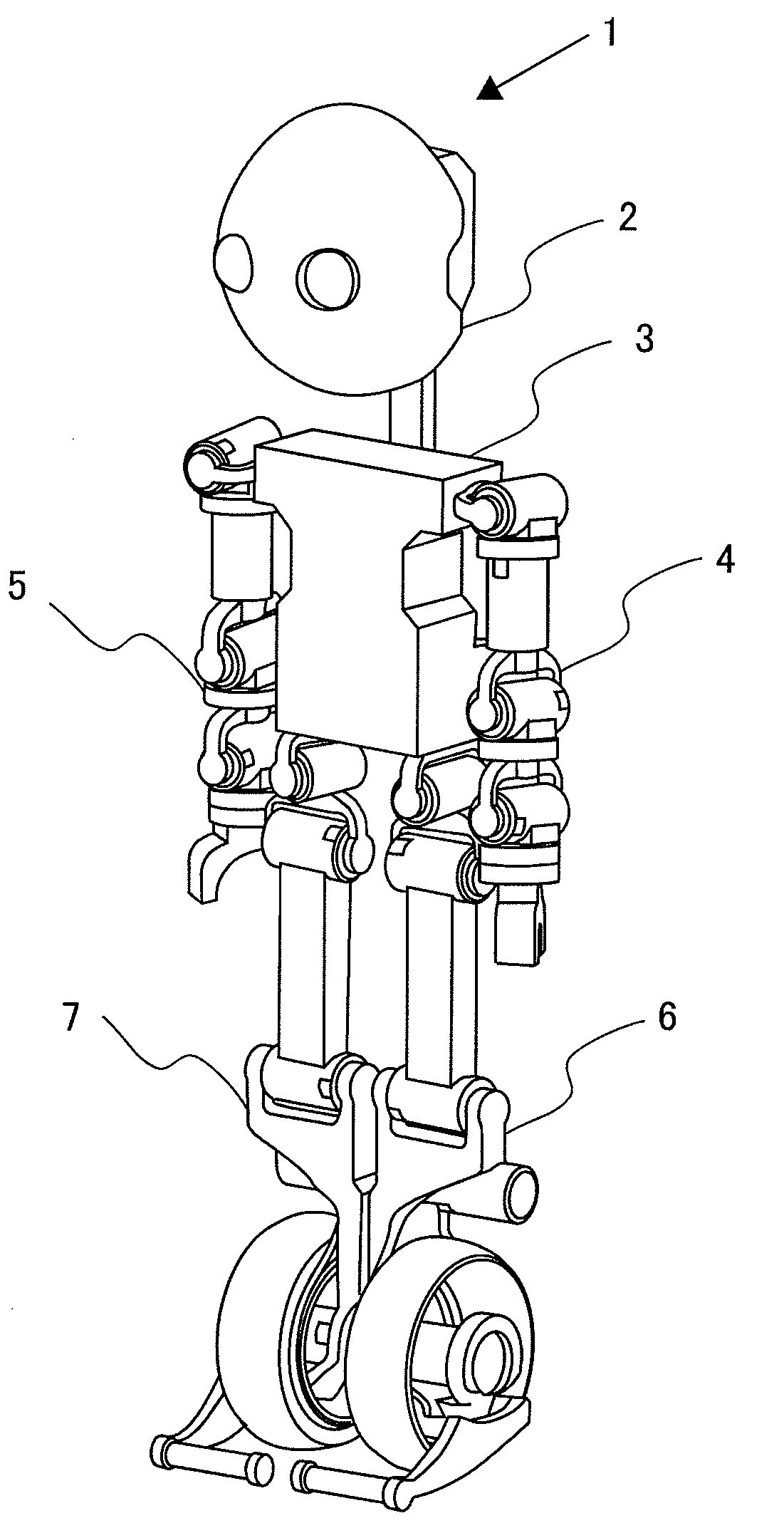
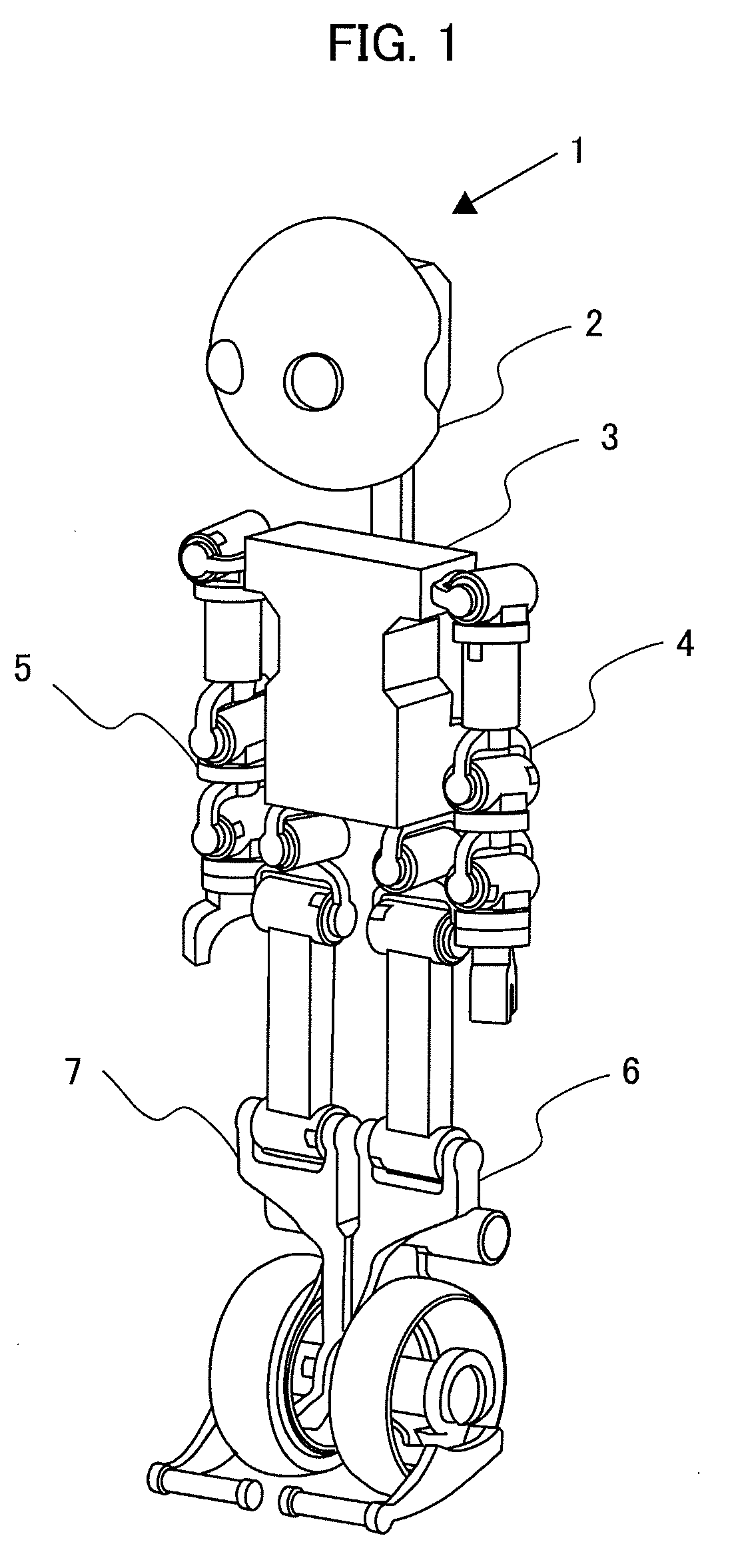
[0022]FIG. 1 is an entire structural view of a robot, according to an embodiment of the present invention.

[0023]In FIG. 1, a robot 1 according to the present invention has two (2) pieces of leg portions, i.e., a left foot 6 and a right foot 7, and a body 3 above them. On both sides of the body 3, it has two (2) pieces of arm portions, i.e., a left arm 4 and the right arm 5. Also, above the body 3 is provided a head portion 2. For example, the left foot 6 and the right foot are used for movement of the robot 1, and the left arm 4 and the right arm 5 are used in workings or operations, such as, holding or grasping a matter, etc. The body 3 comprises a controller apparatus for controlling the operation of each portion, and sensors for detecting an inclination angle of the body to the direction of gravity and an angular velocity.

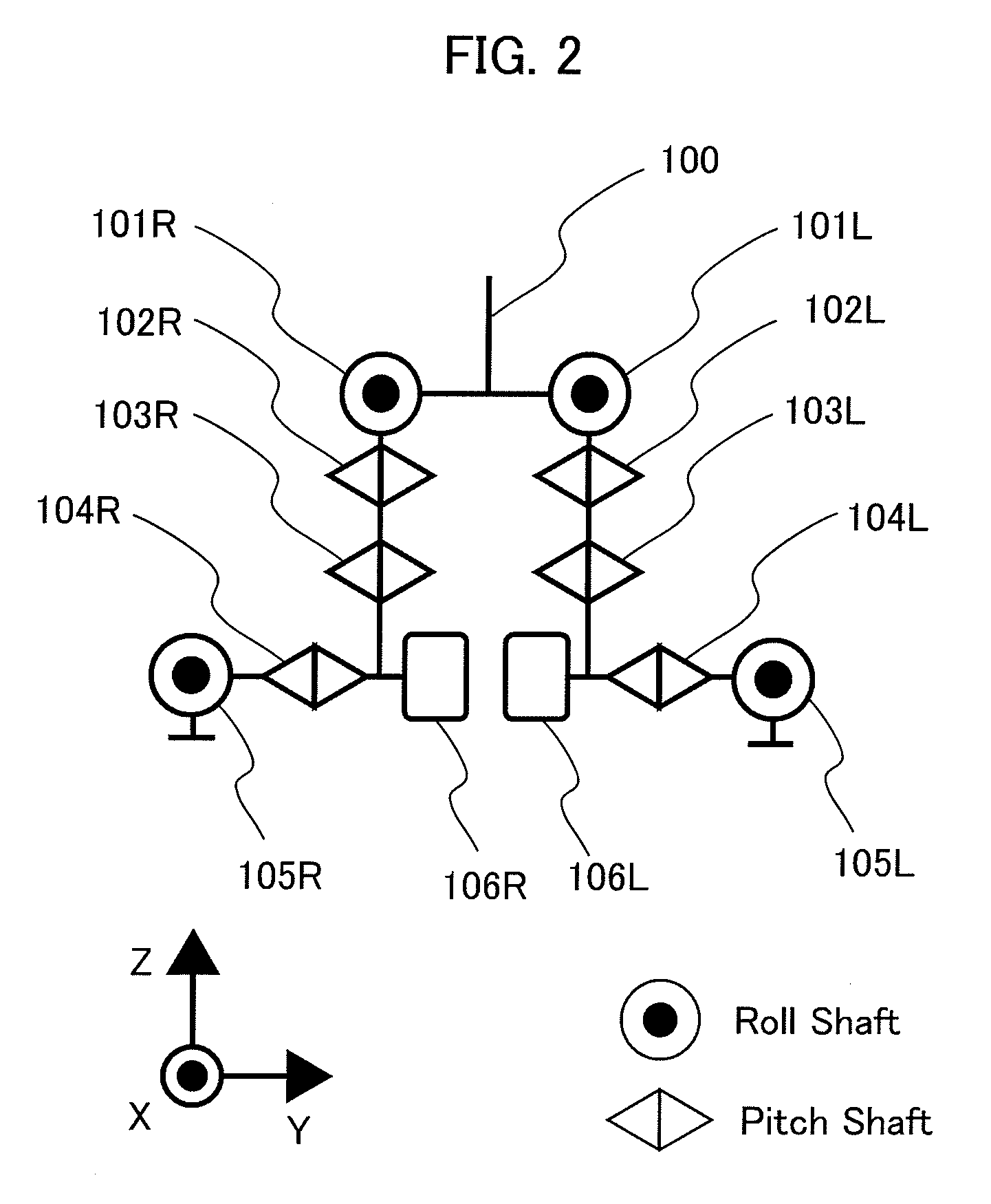
[0024]FIG. 2 is a vie...


PUM


Abstract

A robot having a leg mechanism having high rigidity, so as to enable moving on wheels, on the leveled ground, and also moving on the bipedalism, on the unleveled ground, and also enabling to execute exchanging between the wheel running and the bipedalism in a short time, comprising: a body; and left and right leg portions in lower portion of the body, wherein each leg portion has a wheel, which can be drive, at a tip thereof, and a supporting portion, which is movable in roll and pitch directions, the each leg portion has three (3) degrees of freedom, roll, pitch and pitch from the body side, and the supporting portion has at least two (2) of contact points to be in contact with a ground, and makes up a stable region by a contact point of the wheel and the contact point of the supporting body, and thereby oscillating the left and right leg portions, alternately, so as to make bipedalism, and further operating the supporting body, so as to run on the wheels.

Description

BACKGROUND OF THE INVENTION[0001]The present invention relates to a robot equipped with a mobile apparatus, in particular, a mobile capacity, for automatically conducting an operation or work to be a target.[0002]In relation to a robot having a mobile mechanism for enabling to move on a level ground or an unleveled ground, a humanoid robot is disclosed in the following Patent Document 1. In this Patent Document 1 is disclosed the humanoid robot, equipped with a driving wheels at portion corresponding to the soles of feet, so that it can run on the level ground, by means of the wheels through conducting an inverted pendulum control, while on the unleveled ground, with using the side surfaces of the feet as the soles, by turning roll shafts of ankles by 90 degrees, thereby conducting bipedalism.[0003][Patent Document 1] Japanese Patent Laying-Open No. 2005-288561 (2005).BRIEF SUMMARY OF THE INVENTION[0004]However, with such the method as was mentioned above, because of much degrees of...

Claims


Application Information

Patent Timeline
Patent Type & Authority Applications(United States)
IPC IPC(8): B62D57/028
CPCB62D57/028B25J9/06B25J5/00
Inventor AMINO, AZUSATAMAMOTO, JUNICHINAKAMURA, RYOSUKE
Owner HITACHI LTD
Why Eureka
Try Eureka