Particle therapy

a particle therapy and particle technology, applied in the field of particle therapy system, can solve the problem of limited imaging spa

Inactive Publication Date: 2009-05-07
SIEMENS AG
View PDF12 Cites 20 Cited by
  • Summary
  • Abstract
  • Description
  • Claims
  • Application Information

AI Technical Summary

Benefits of technology

[0023]In one embodiment, the distance between the treatment room isocenter for irradiation and for imaging is equal to or less than 2 m and, if possible, less than 0.5 m, and so the verification of position can also be undertaken repeatedly when possible during an irradiation without

Problems solved by technology

Only limited space is available for imaging.
Such imaging devices for obtaining 3D image dat

Method used


Image

  • Particle therapy
  • Particle therapy
  • Particle therapy

Examples


Embodiment Construction

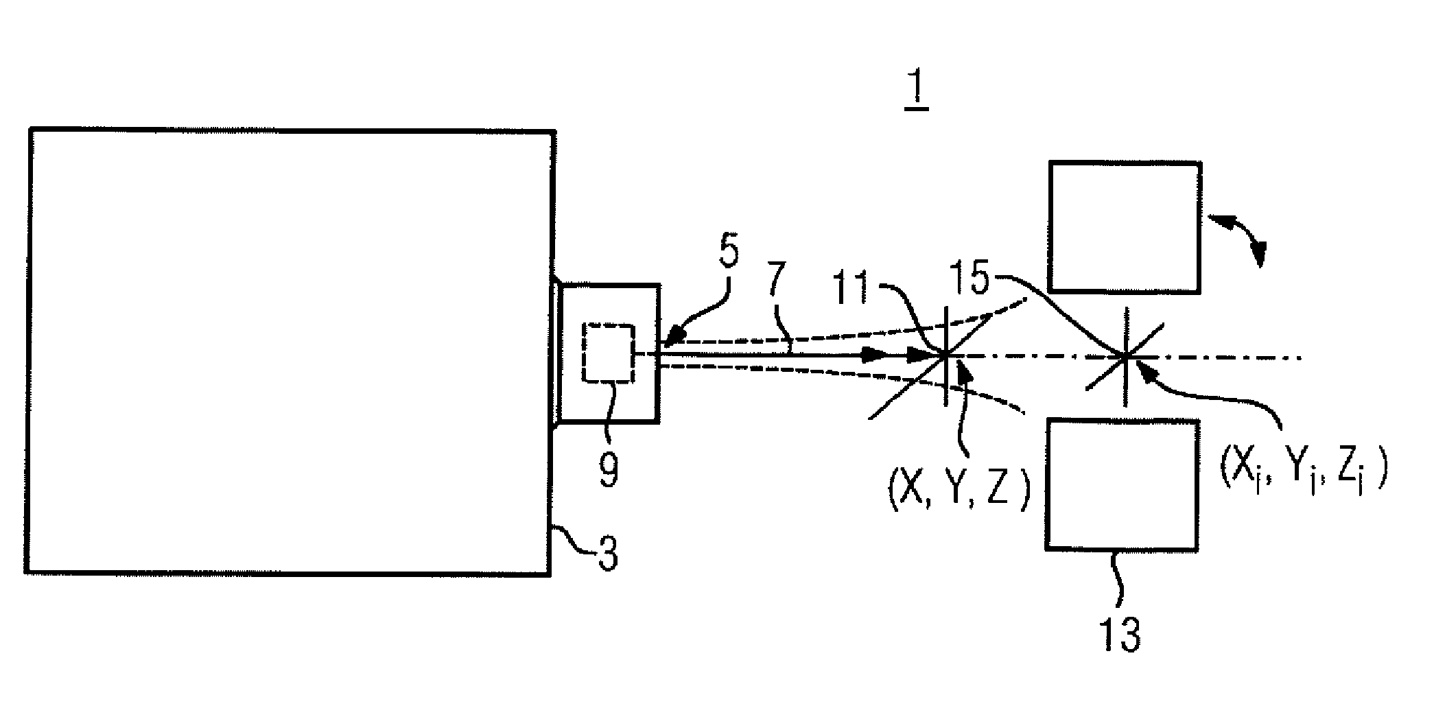
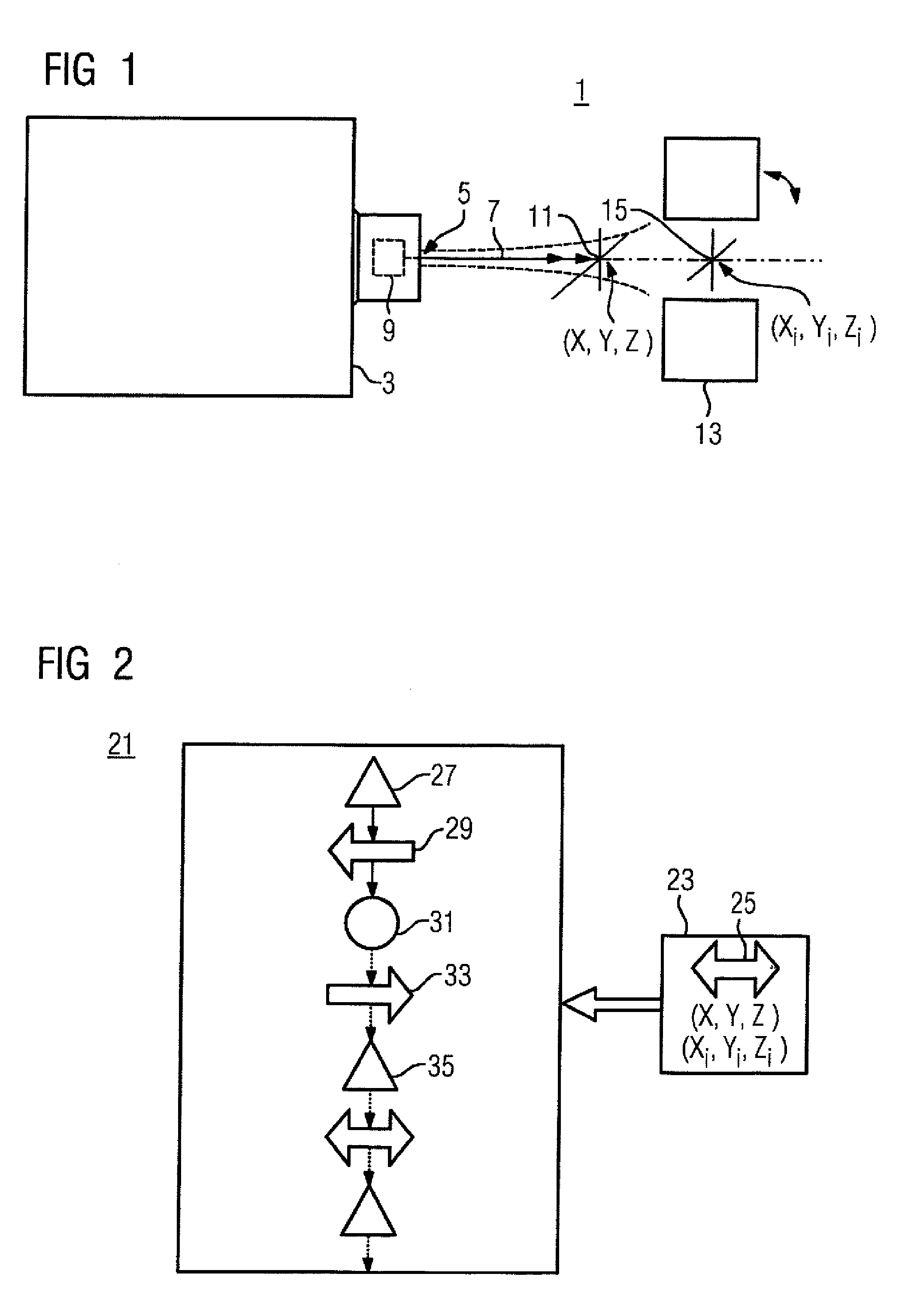
[0032]FIG. 1 shows a particle therapy system 1 for irradiating a volume, to be irradiated, of a patient with high energy particles. A particle accelerating unit 3 emits a particle beam 7 from a beam exit 5. The particle therapy system includes, for example, a raster scanning apparatus 9 that scans a scanning region of 20 cm×20 cm. A treatment room isocenter 11 may be set on a beam central axis that runs centrally in relation to the scanning region. The particle beam diverges because of scattering processes in the beam or with the matter being X-rayed. The closer a treatment room isocenter is arranged to the beam exit 5, the smaller the beam diameter of the particle distribution in the particle beam, and the more sharply defined the lateral drop in the particle distribution. A spacing of 60 cm may be selected in the case of irradiation with protons. At this spacing, the beam diverges to a desired beam diameter adopted in the therapy plan; for example, the irradiation is performed usi...


PUM


Abstract

The invention relates to a treatment room for a particle therapy system that has a treatment room isocenter, which can be set variably during treatment and forms an origin of a coordinate system, and a patient positioning apparatus for automatically positioning the patient with reference to the set treatment room isocenter.

Description

[0001]The present patent document is a nationalization of PCT / EP2006 / 068308, filed Nov. 9, 2006, designating the United States, which is hereby incorporated by reference. This application also claims the benefit of EP 05024743.6, filed Nov. 11, 2005, which is hereby incorporated by reference.BACKGROUND[0002]The present embodiments relate to a particle therapy system for irradiating a volume of a patient that is to be irradiated with high energy particles. The present embodiments may also relate to the planning and carrying out of irradiation in a treatment room of a particle therapy system.[0003]A particle therapy system has at least one treatment room with a beam exit from which a particle beam emerges in order to interact with the patient positioned in an irradiation position. Usually, the irradiation position is given with reference to an irradiation isocenter of the particle therapy system. Furthermore, the particle therapy system usually has an imaging apparatus for verifying t...

Claims


Application Information

Patent Timeline
IPC IPC(8): A61N5/00
CPCA61N5/103A61N5/1043A61N5/1049A61N5/1065A61N2005/1087A61N5/1078A61N2005/1061A61N2005/1063A61N5/1069
Inventor GROZINGER, SVEN OLIVERHERMANN, KLAUSRIETZEL, ELKESOMMER, ANDRESZEUNER, TORSTEN
Owner SIEMENS AG
Why Eureka
Try Eureka