
Multiple Image Collection and Synthesis for Personnel Screening

Inactive Publication Date: 2009-05-07
AMERICAN SCI & ENG INC
View PDF55 Cites 95 Cited by
  • Summary
  • Abstract
  • Description
  • Claims
  • Application Information

AI Technical Summary

Benefits of technology

[0010]In accordance with preferred embodiments of the present invention an apparatus is provided that ascertains a material feature associated with a subject, and in certain embodiments, generates one or more images of the subject. The apparatus generally includes a first carriage, a second carriage, at least one vertical positioner, and at least one detector. Each carriage includes a source that is adapted to produce

Problems solved by technology

Current personnel screening systems using backscatter and millimeter wave technology can provide images representative of the surface of the scanned subject, but, insofar as they may well not penetrate the entirety of the scanned subject, they lack the capability to image items of interest located on the far side of the subject, or items of interest that return a signal response similar to the background surrounding the subject, or items artfully concealed on the subject.
These additional scanning requirements, while possibly increasing detection accuracy, significantly reduce the rate of throughput of such systems that are generally implemented under circumstances that experience large volumes of scanning.

Method used


Image

  • Multiple Image Collection and Synthesis for Personnel Screening
  • Multiple Image Collection and Synthesis for Personnel Screening
  • Multiple Image Collection and Synthesis for Personnel Screening

Examples


Embodiment Construction

[0049]Definitions. As used in this description and the accompanying claims, the following terms shall have the meanings indicated, unless the context otherwise requires:

[0050]A “carriage” is a moveable system including a source and / or a detector of penetrating radiation. A carriage may include a detector that detects radiation; however, it is not required to.

[0051]A “vertical positioner” is a system component capable of displacing a carriage in a direction having a vertical component. A positioner may include an actuator, such as a motor, and attendant mechanical linkages or couplings.

[0052]A “vertically disposed array” is a plurality of objects, generally sources or detectors, disposed in a configuration having a vertical component such that at least one source in a vertically disposed array of sources is at a different elevation than at least one other source in the same vertically disposed array.

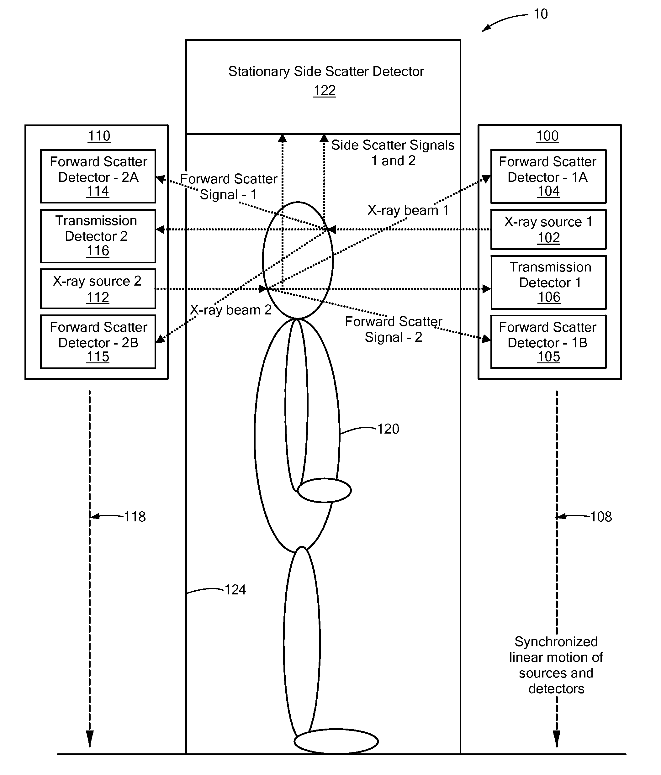
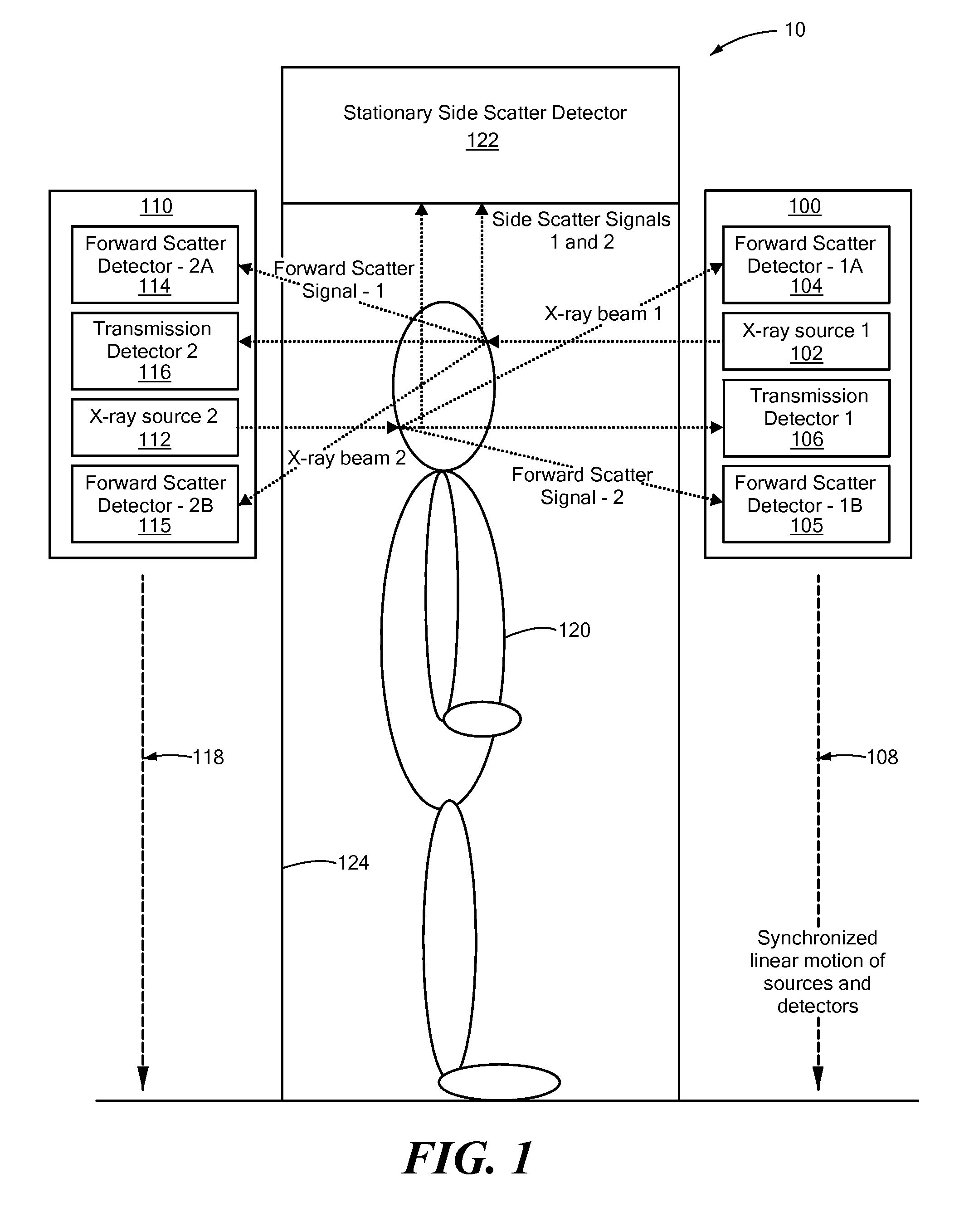
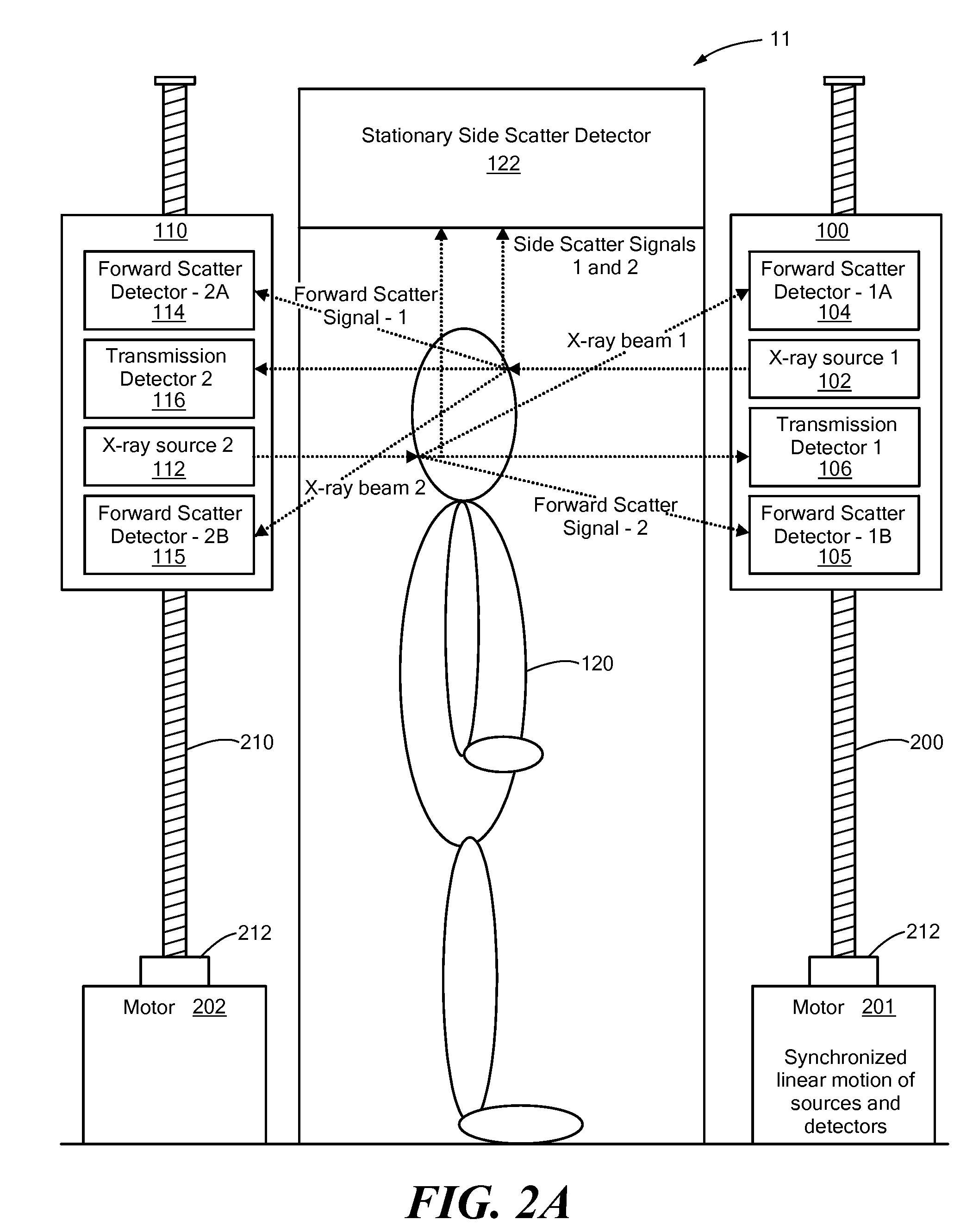
[0053]FIG. 1 is a schematic view of an embodiment of the present invention scanning a...


PUM


Abstract

An apparatus and method for inspecting personnel or their effects. A first and second carriage each carries a source for producing a beam of penetrating radiation incident on a subject. A positioner provides for synchronized relative motion of each carriage vis-à-vis the subject in a direction having a vertical component. A detector receives radiation produced by at least one of the sources after the radiation interacts with the subject.

Description

CROSS REFERENCE TO RELATED APPLICATIONS[0001]The present application is a continuation-in-part application of U.S. patent application Ser. No. 11 / 737,317, filed Apr. 19, 2007, and like that application the present application claims priority to U.S. Provisional Application No. 60 / 794,295, filed Apr. 21, 2006.[0002]The present application is also a continuation-in-part application of U.S. patent application Ser. No. 12 / 171,020, filed Jul. 10, 2008, which is a continuation application of U.S. patent application Ser. No. 11 / 097,092, filed Apr. 1, 2005 and issued Jul. 15, 2008 as U.S. Pat. No. 7,400,701. The present application, like application Ser. Nos. 12 / 171,020 and 11 / 097,092, claims priority to U.S. Provisional Application No. 60 / 561,079, filed Apr. 9, 2004.[0003]The present application also claims priority to U.S. Provisional Application No. 60 / 988,933, filed Nov. 19, 2007.[0004]All of the foregoing applications and patents are hereby incorporated by reference herein in their ent...

Claims


Application Information

Patent Timeline
IPC IPC(8): G01N23/203G01N23/201
CPCG01N23/201G01N23/203G01N23/20083G01V5/0025G01V5/0008G01V5/0016G01V5/222G01V5/22G01V5/20
Inventor MASTRONARDI, RICHARDFLEURY, DEANSCHUBERT, JEFFREY R.DIMARE, JOSEPHSCHUELLER, RICHARDCHALMERS, ALEXANDER
Owner AMERICAN SCI & ENG INC
Features
  • Generate Ideas
  • Intellectual Property
  • Life Sciences
  • Materials
  • Tech Scout
  • Unparalleled Data Quality
  • Higher Quality Content
  • 60% Fewer Hallucinations
Learn More