Tree timming apparatus

a technology of trimming apparatus and cutting blade, which is applied in the field of tree trimming devices, can solve the problems of loosening of the cutting blade from its mount, increasing the tendency of the cutting blade to twist or jam, etc., and achieves the effect of increasing the mechanical advantage of cutting or shearing blade operation and increasing the mechanical advantag

Inactive Publication Date: 2009-05-14
MONNIG GARY J +2
View PDF19 Cites 3 Cited by
  • Summary
  • Abstract
  • Description
  • Claims
  • Application Information

AI Technical Summary

Benefits of technology

[0003]Briefly and in general terms, the present invention provides for a tree trimming apparatus that includes a cutting head assembly with a hook member and a cutting or shearing blade, adapted to be mounted to the end of a pole by a mounting bracket. A main lever arm is pivotally mounted at a first end to a support arm of the hook, and a pulley receiving a rope for manual operation of the cutting or shearing blade is connected to the main lever arm for increased mechanical advantage in operation of the cutting or shearing blade. First and second parallel spaced apart link members are pivotally connected at their upper end portions to first and second sides of the blade lever arm, and are pivotally connected at their lower end portions to the first and second sides of the main lever arm, medially and near an end of the main lever arm, to provide further increased mechanical advantage by compound lever action on the lever arm of the cutting blade. A coil return spring is connected between the lever arm of the cutting blade and a point on the main lever arm medially of the link members. The placement of the parallel spaced apart link members on either side of the cutting blade and on either side of the main lever arm provides for a uniform, non-twisting force on the cutting blade during actuation of the cutting assembly.

Problems solved by technology

Increasing the mechanical advantage of such tree trimming and pruning devices can result in twisting or jamming of the cutting blade particularly when strong force is applied to move the cutting blade, and can result in loosening of the cutting blade from its mount and an increasing tendency of the cutting blade to twist or jam when strong force is applied to the cutting mechanism.

Method used


Image

  • Tree timming apparatus
  • Tree timming apparatus
  • Tree timming apparatus

Examples


Embodiment Construction

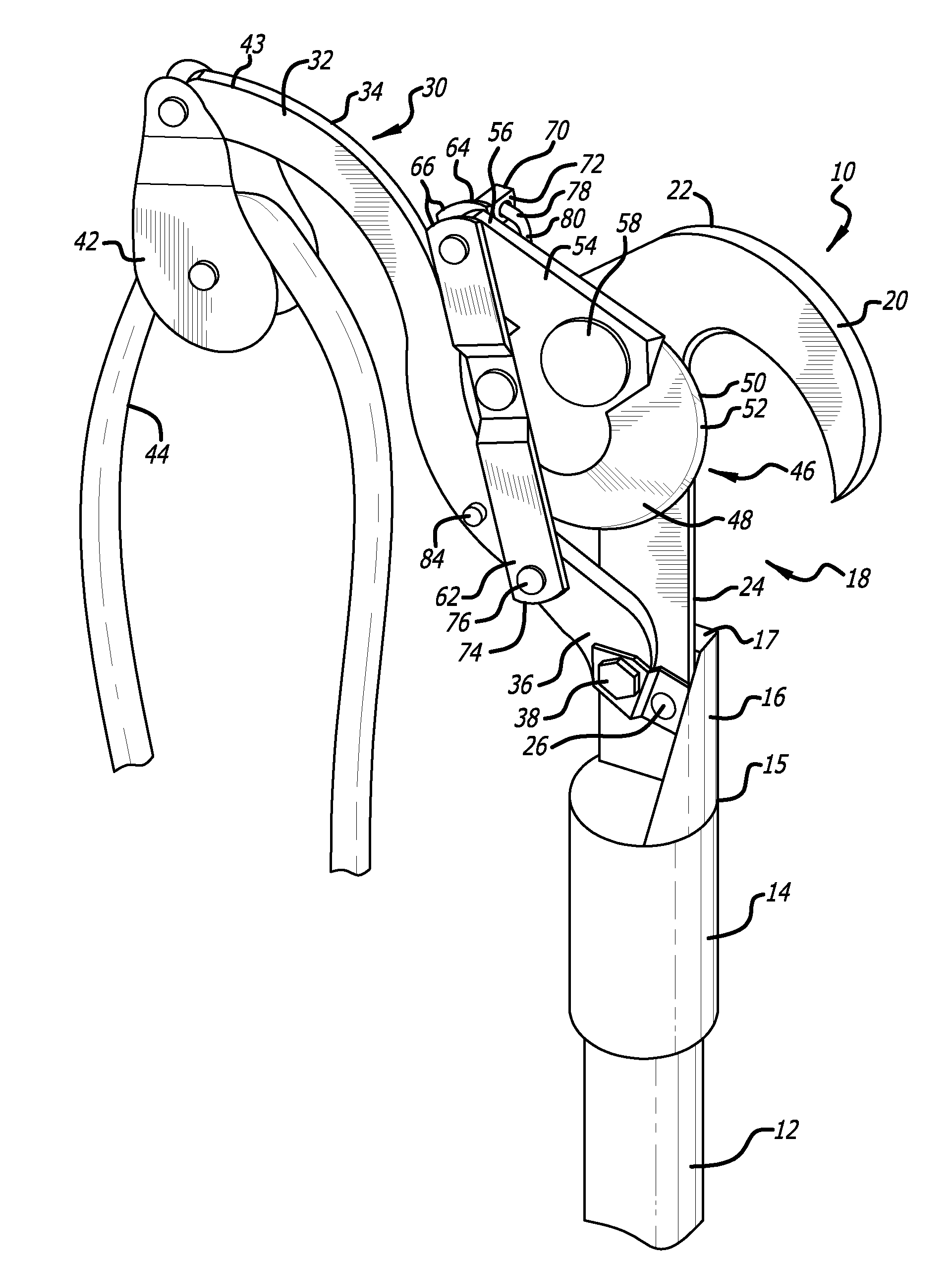
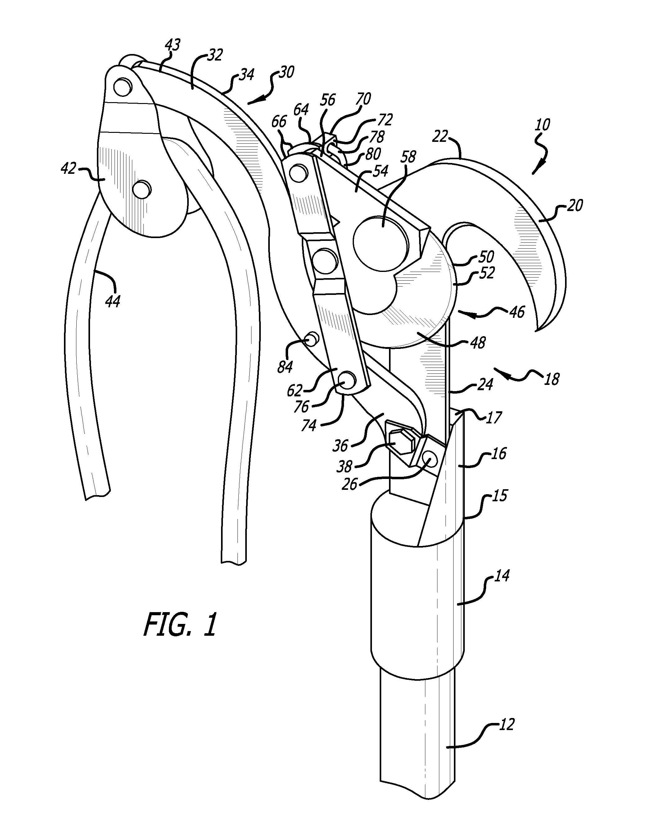
[0010]As is illustrated in FIG. 1, the present invention provides for a tree trimming apparatus 10 adapted to be mounted to an end of a pole or pole assembly 12, only a portion of which is shown, by a mounting bracket 14 adapted to fit over an end of the pole assembly, and optionally including a clamp or one or more fasteners (not shown) for connecting the mounting bracket to the pole. The mounting bracket is connected at one end 15 of the mounting bracket to the pole, and a flange or support post 16 extends from the other end 17 of the mounting bracket and is connected to the cutting head assembly 18.

[0011]The cutting head assembly includes a hook 20 having a head end 22 and a support arm 24 mounted by one or more fasteners 26, such as rivets, bolts or screws, to the flange or support post of the mounting bracket. As will be further explained below, a main lever arm 30 having planar sides 32, 34, is also pivotally mounted at a first end 36 to the support arm of the hook as well as ...


PUM


Abstract

The tree trimming apparatus includes a cutting head assembly adapted to be mounted to the end of a pole by a mounting bracket. A main lever arm is pivotally mounted at a first end to a support arm of a hook of the cutting head assembly, and a pulley receiving a rope for manual operation of the cutting or shearing blade is connected to the main lever arm. First and second parallel spaced apart link members are pivotally connected at their upper end portions to first and second sides of the blade lever arm, and are pivotally connected at their lower end portions to the first and second sides of the main lever arm, medially and near an end of the main lever arm. A coil return spring is connected between the lever arm of the cutting blade and a point on the main lever arm medially of the link members.

Description

BACKGROUND OF THE INVENTION[0001]The present invention relates generally to tree trimming devices, and more particularly relates to a tree trimming apparatus with increased mechanical advantage for manual operation.[0002]A conventional tree trimming and pruning apparatus includes an elongated pole or handle and a manually operated cutting head assembly mounted to an end of the pole. The cutting head assembly typically includes a hook and a blade cooperatively mounted adjacent to the hook for a shearing or scissoring action when the blade is actuated. A lever arm of the blade is conventionally directly connected to a rope or handle, and a return spring may be connected to the blade for returning the blade to a ready position after a cutting action has been accomplished. Increasing the mechanical advantage of such tree trimming and pruning devices can result in twisting or jamming of the cutting blade particularly when strong force is applied to move the cutting blade, and can result ...

Claims


Application Information

Patent Timeline
Patent Type & Authority Applications(United States)
IPC IPC(8): A01G3/025A01G3/08
CPCA01G3/0255
Inventor MONNIG, GARY J.PAQUET, JULES P.PAQUET, MARC J.
Owner MONNIG GARY J
Why Eureka
Try Eureka