
Cooler for spatially confined cooling

a cooling device and spatially restricted technology, applied in the field of cooling devices, can solve the problems of difficult contact between cooling blocks and various types of surfaces, uneven surfaces, and difficulty in direct installation of cooling blocks on various electronic devices,

Inactive Publication Date: 2009-05-14
KOOLANCE
View PDF6 Cites 31 Cited by
  • Summary
  • Abstract
  • Description
  • Claims
  • Application Information

AI Technical Summary

Benefits of technology

[0008]In some embodiments, the deformable pouch for each cooling unit is connected to an inlet connection nozzle and an outlet connection nozzle, with a space between the inlet connection nozzle and the outlet connection nozzle being off-centered with respect to a longitudinal axis of the deformable pouch. Also, or alternatively, a casing for the deformable pouch can have an opening through which the inlet connection nozzle can extend and an opening through which the outlet connection nozzle extend, and a space between the openings can be off-centered with respect to a longitudinal axis of the casing. In some embodiments of the present invention, the off-centered position of the space between the connection nozzles, or between openings on the casing, can allow the cooling jacket units to be positioned adjacent other cooling jacket units without resulting in conflicting space requirements for fittings associated with the connection nozzles.

Problems solved by technology

Since the conventional cooling blocks are formed of hard materials such as metal in consideration of heat conductivity, it is difficult to make them contact various types of surfaces, e.g., uneven surfaces.
Also, due to limitation in installation space, the cooling blocks are difficult to directly install on the various electronic devices such as hard disk drives, video cards or memory cards and a PCB.
However, such adhesive devices are mechanically complex.
However, it has been observed by the inventor(s) hereof, that the casing and connection devices for the pouch body for the soft cooling jacket can be obstructive when space confines are encountered.
As such, efficient utilization of space on the slot connector is impaired, limiting the number of PCBs that can be connected to both the soft cooling jacket and slot connector simultaneously.

Method used


Image

  • Cooler for spatially confined cooling
  • Cooler for spatially confined cooling
  • Cooler for spatially confined cooling

Examples


Embodiment Construction

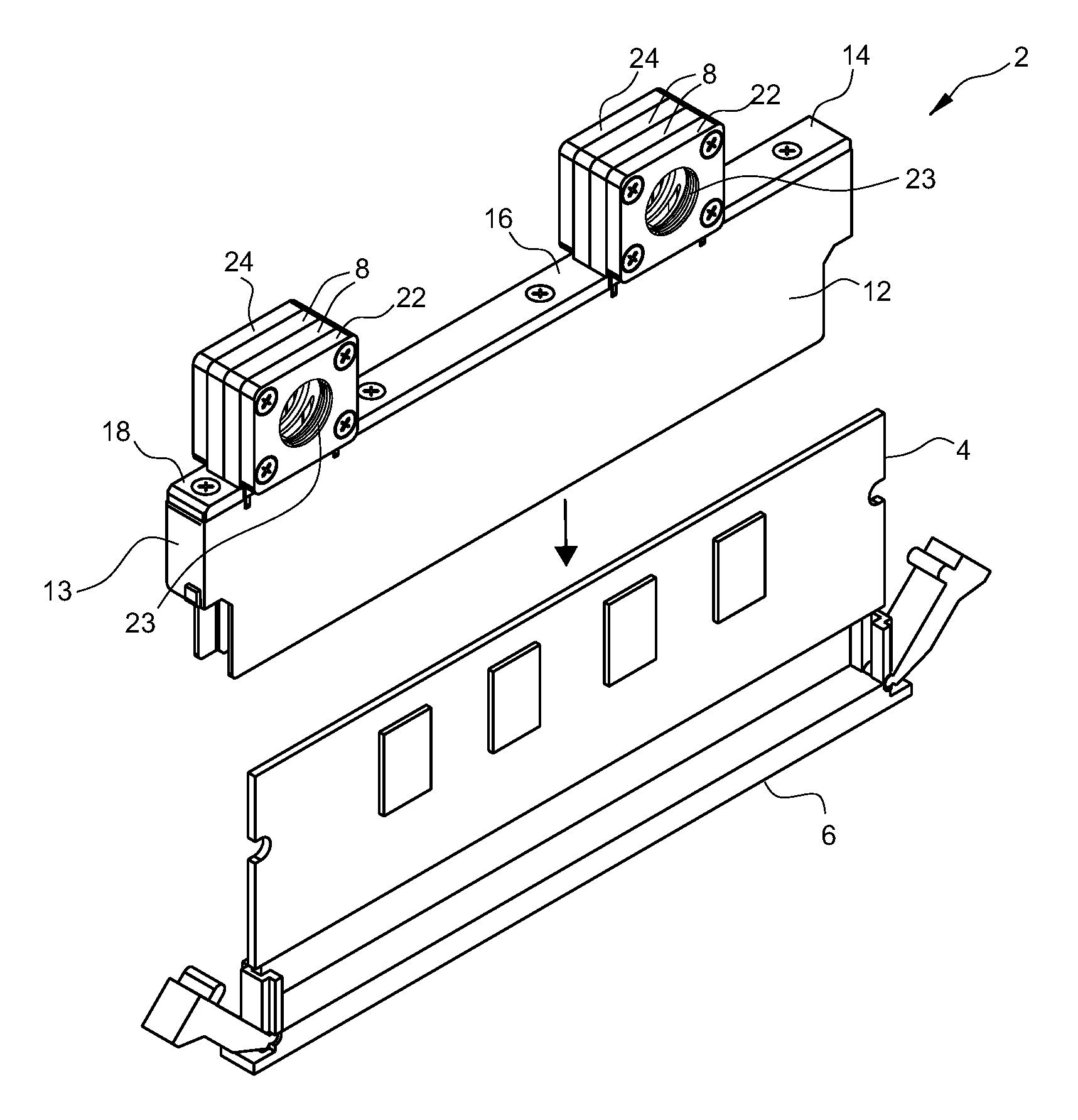
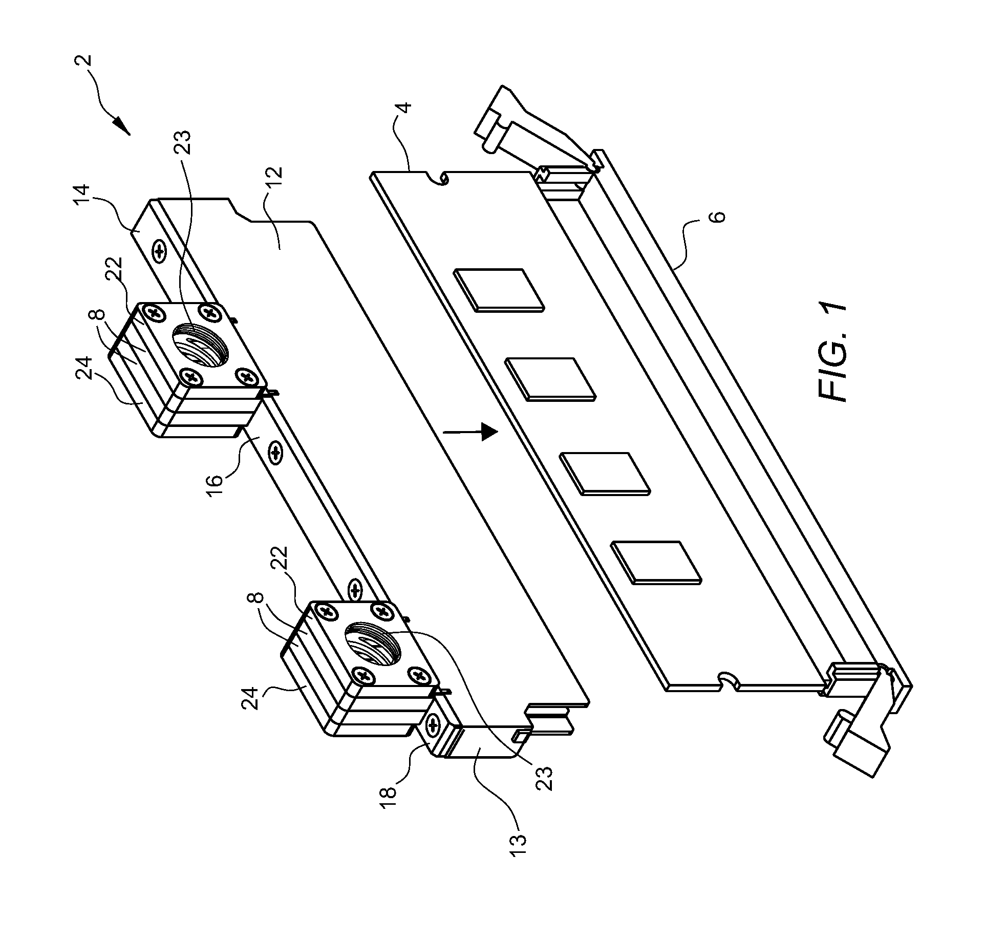
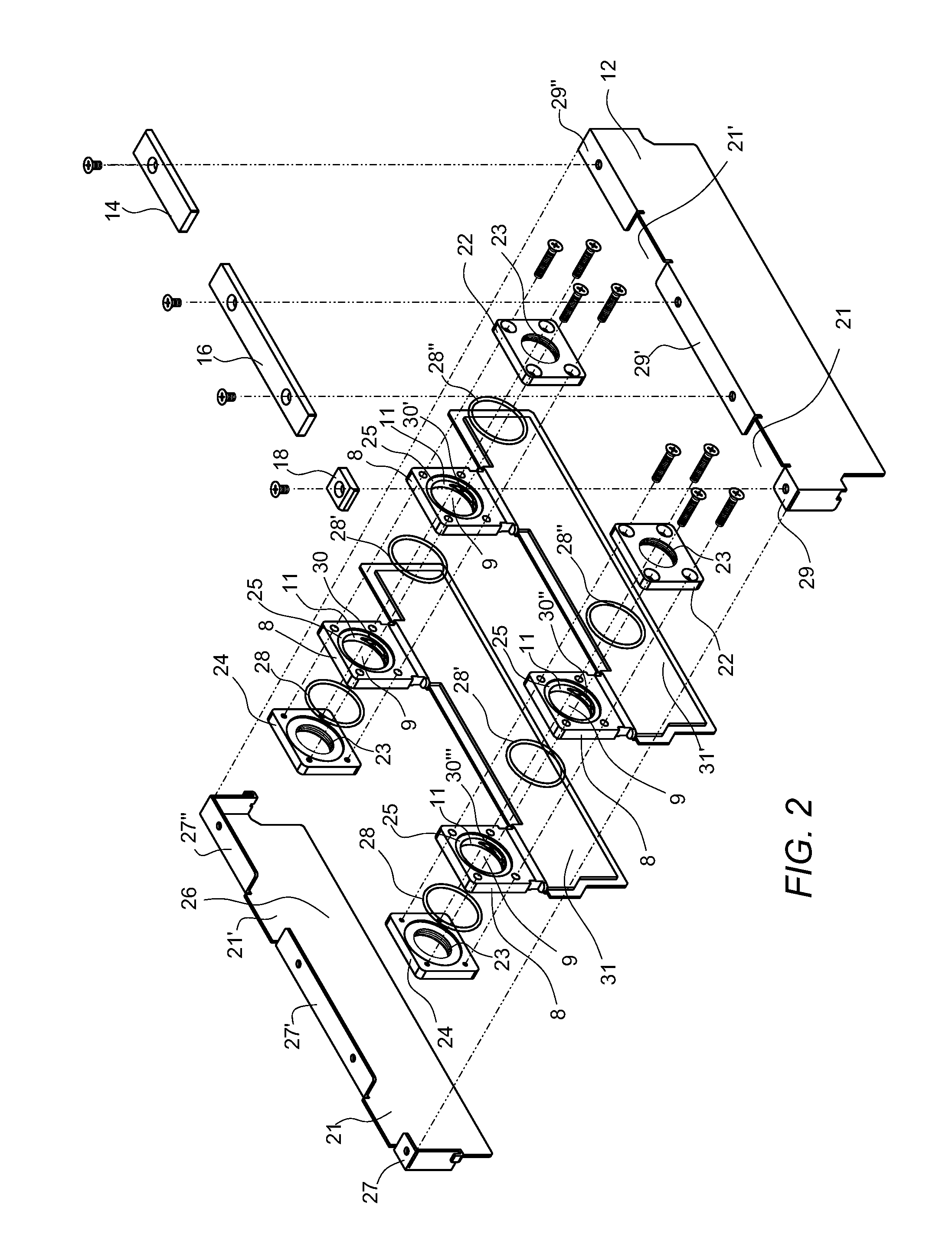
[0020]In the following description, certain specific details are set forth in order to provide a thorough understanding of various embodiments of the invention. However, upon reviewing this disclosure, one skilled in the art will understand that the invention may be practiced without many of these details. In other instances, well-known structures related to cooling systems, heat generating electrical components, and materials of construction therefore have not been described in detail to avoid unnecessarily obscuring the descriptions of the embodiments of the invention.

[0021]U.S. Pat. No. 7,167,366 discloses a liquid cooling type, cooling jacket for an electronic device, and is hereby incorporated by reference in its entirety. The cooling jacket is adapted to various shapes of heat-generating elements having uneven surfaces and various shapes of installation spaces. The cooling jack can include a pouch body formed of a soft, loose elastic material that is deformable to closely cont...


PUM


Abstract

A plurality of cooling units for cooling electrical components can be disposed in close proximity to one another in confined spaces with minimal space conflict, due to the design of the cooling units that allows for staggered position of connection fittings. Also, the cooling units can be selectively arranged in a plurality of configurations with respect to one another, while being fluidly connected.

Description

BACKGROUND[0001]1. Field of the Invention[0002]The present invention relates to coolers, and more particularly, to cooling jacket units and assemblies that are spatially efficient for cooling one or more small electrical components.[0003]2. Description of Related Art[0004]In general, in order to cool various heat-generating elements such as semiconductor chips or electronic devices in a liquid cooling manner, a surface contacting a heat-generating element has been made of metal and cooling blocks in which a coolant circulates have been used. Since the conventional cooling blocks are formed of hard materials such as metal in consideration of heat conductivity, it is difficult to make them contact various types of surfaces, e.g., uneven surfaces. Also, due to limitation in installation space, the cooling blocks are difficult to directly install on the various electronic devices such as hard disk drives, video cards or memory cards and a PCB. In order to increase close adhesion, variou...

Claims


Application Information

Patent Timeline
IPC IPC(8): F28F7/00F28D15/00H02B1/56
CPCH05K7/20254
Inventor CHEON, PETERSONG, ANKUKPARK, JEASUNGLEE, EUNGSOONHUNTING, TIM
Owner KOOLANCE
Features
  • Generate Ideas
  • Intellectual Property
  • Life Sciences
  • Materials
  • Tech Scout
  • Unparalleled Data Quality
  • Higher Quality Content
  • 60% Fewer Hallucinations
Learn More