Casing head slip lock connection for high temperature service

a technology of high temperature service and slip lock connection, which is applied in the direction of fluid pressure sealing joints, pipe supports, fluid removal, etc., can solve the problems of installation errors, large time and labor, and inability to find experienced welders

Active Publication Date: 2009-05-14
STREAM FLO INDS
View PDF15 Cites 11 Cited by
  • Summary
  • Abstract
  • Description
  • Claims
  • Application Information

AI Technical Summary

Benefits of technology

[0022]In the preferred embodiments, the casing head of this invention provides a metal seal pressure barrier between the casing head and the surface casing to eliminate the need to weld on the casing head to the casing. The invention is particularly ...

Problems solved by technology

The problems with these methods of attaching the casing head are that they may require extensive time and labour, are often expensive, and create the possibility of installation errors.
Also, experienced welders may not be available.
While one or more elastomeric seals, such as O-ring seals are typically used to seal the central bore of the casing head to the surface casing, in high temperature and/or corrosive environments, these seals can fail.
Duri...

Method used


Image

  • Casing head slip lock connection for high temperature service
  • Casing head slip lock connection for high temperature service
  • Casing head slip lock connection for high temperature service

Examples


Embodiment Construction

[0028]As used herein and in the claims, the word “comprising” is used in its non-limiting sense to mean that items following the word in the sentence are included and that items not specifically mentioned are not excluded. The use of the indefinite article “a” in the claims before an element means that one of the elements is specified, but does not specifically exclude others of the elements being present, unless the context clearly requires that there be one and only one of the elements. For example, the term “a metal seal ring” as used herein and in the claims may include multiple metal seal rings such as a pair.

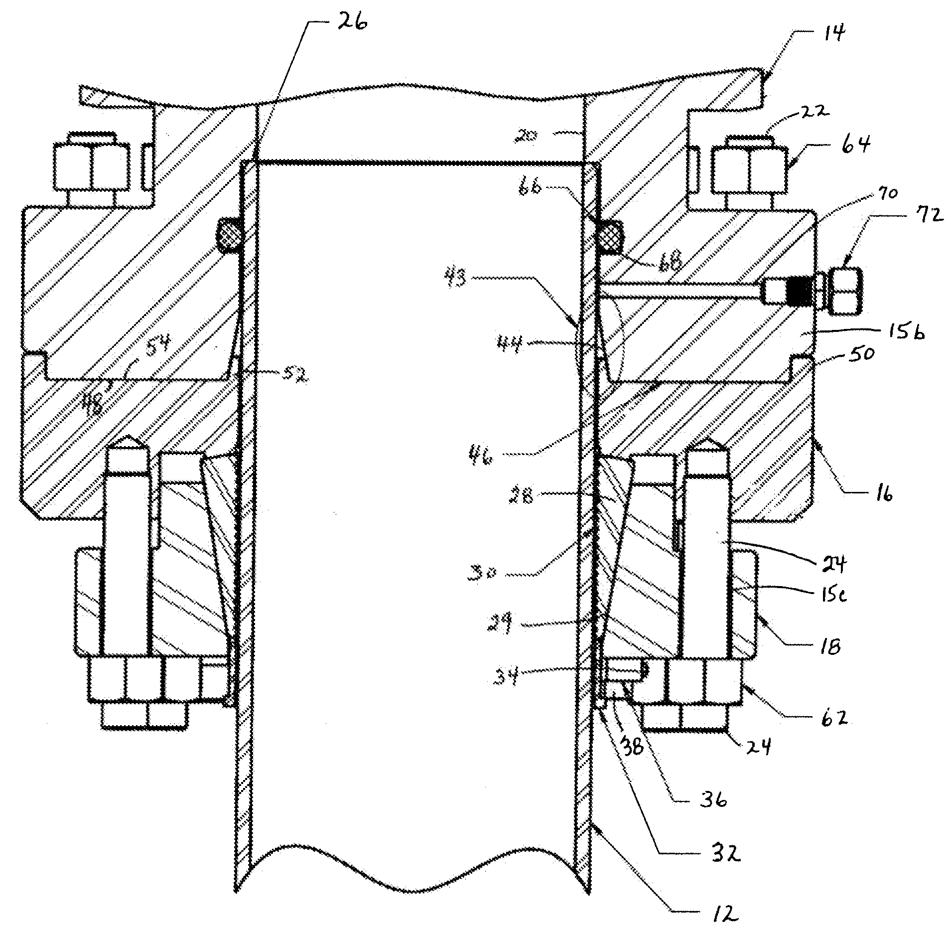
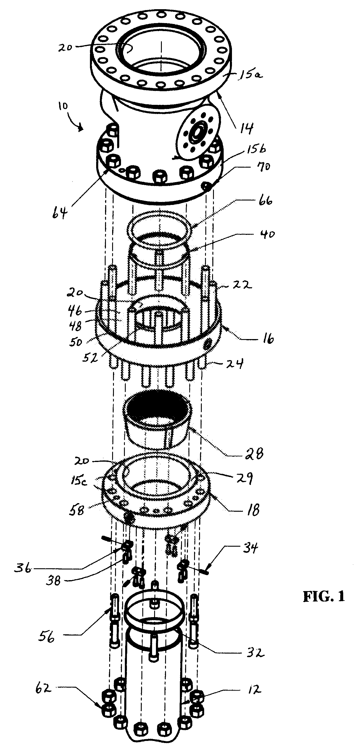
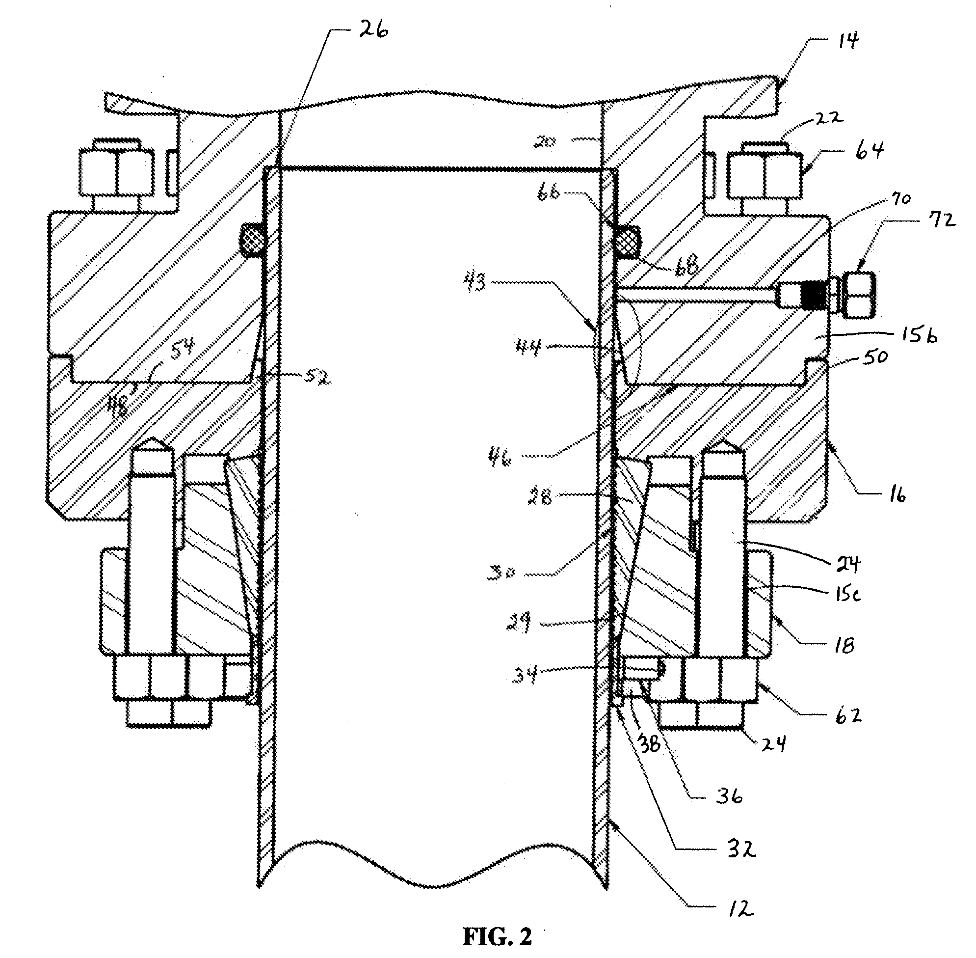
[0029]Having reference to FIG. 1, the casing head of this invention is shown generally at 10 with the components vertically aligned for placement on the surface casing 12. The casing head 10 is shown to include three main generally tubular housing components, in top to bottom stacking order including an upper head housing 14, an annular bottom ring 16, and an annular slip ...


PUM


Abstract

A wellhead connection for connecting and sealing to a casing, including an upper head housing accommodating the upper end of the casing in its central bore, a stop shoulder in the central bore to allow the upper head housing to rest on the upper end of the casing, and a seal profile section formed at the lower end of the central bore below the stop shoulder. The wellhead connection is configured such that, first connecting the slip housing and bottom ring with a bottom connector energizes slip connectors into gripping engagement with the casing and locks the slip housing and bottom ring around the casing, while thereafter connecting the upper head housing and the bottom ring with a top connector energizes the metal seal ring so as to radially compress the metal seal ring against the casing to form a metal seal.

Description

CROSS-REFERENCE TO RELATED APPLICATIONS[0001]This application claims priority from U.S. Provisional Patent Application No. 60 / 987,676 filed Nov. 13, 2007, which is incorporated by reference herein to the extent that there is no inconsistency with the present disclosure.BACKGROUND OF THE INVENTION[0002]This invention relates to a wellhead connection to casing. The invention also extends to a method of making the wellhead connection.[0003]The lower part of a wellhead is called a casing head or tubing head, hereinafter termed casing head. The casing head is attached to a casing (pipe) and provides a connection to the wellhead equipment located thereabove. The connection must be able to seal well pressure and transmit mechanical loads in any direction. Common connections to a casing are either by threading or by welding. For high temperature service the common connection is welding. The problems with these methods of attaching the casing head are that they may require extensive time and...

Claims


Application Information

Patent Timeline
IPC IPC(8): E21B33/04E21B33/03
CPCE21B33/04E21B33/03
Inventor KHAZANOVICH, ABRAMKHAZANOVICH, IRINA
Owner STREAM FLO INDS
Why Eureka
Try Eureka