Multi-coaxial cable assembly and manufacturing method of the same
Inactive Publication Date: 2009-05-14
HITACHI CABLE
View PDF2 Cites 20 Cited by
Summary
Abstract
Description
Claims
Application Information
AI Technical Summary
This helps you quickly interpret patents by identifying the three key elements:
Problems solved by technology
Method used
Benefits of technology
Benefits of technology
[0025]The present invention provides the multi-coaxial cable assembly and the manufacturing method of the same, capable of simplifying a connection work between a plurality of coaxial cables and the wiring pattern of the wiring board or the connector, and capable of reducing positioning accuracy required for connection.
Problems solved by technology
Moreover, in recent years, further superfine coaxial cables have been progressed, and it is difficult to maintain a parallel state capable of performing a sufficient positioning of the external conductors, the insulators, the center conductors of the plurality of coaxial cables in a state of exposing terminal connection parts, with respect to the wiring patterns of the printed board or the connector.
However, wider area of the wiring pattern for connecting to the printed board or the connector is required, and the accuracy required for positioning is not different from the related art shown in FIG. 12.
Therefore, there is a problem that accuracy more than that of the related art shown in FIG. 12 is required for positioning at the time of connection.
Method used
Image
Click on the blue label to locate the original text in one second.
Reading with bidirectional positioning of images and text.
Examples
first embodiment
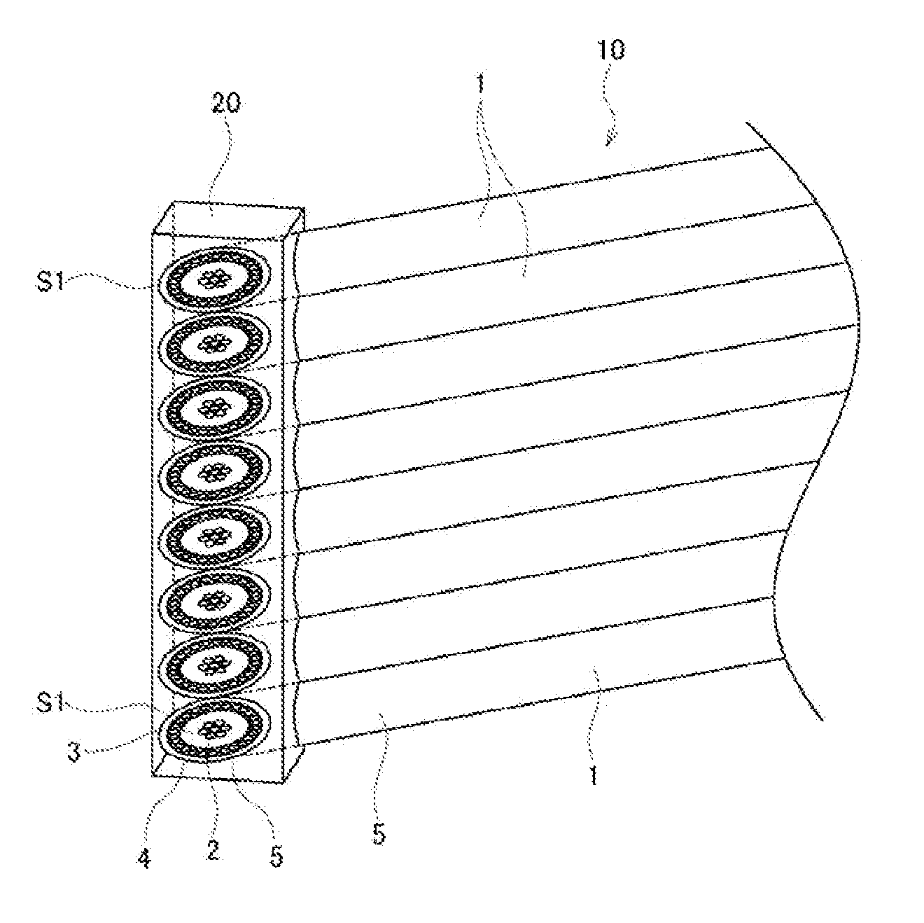
[0045]A first embodiment of the multi-coaxial cable assembly and the manufacturing method of the same according to the present invention will be explained by using FIG. 1 to FIG. 4.
[0046]As illustrated in FIG. 1, in superfine coaxial cables 1 used in this embodiment, outer peripheries of center conductors (inner conductors) 2 are coated with insulators (inner insulators) 3, external conductors (shields, outer conductors) 4 and jackets (sheaths, outer insulators) 5, respectively, with these insulators 3, external conductors 4, and jackets 5 concentrically arranged in the outer peripheries of the center conductors 2 having circular sections.
[0047]Each center conductor 2 is a strand wire formed by a plurality of wires composed of a copper wire or a copperalloy wire plated with Sn and Ag, for example. Specifically, the center conductor 2 is composed of seven strand wires, with each wire having a diameter of 0.013 mm (corresponding to 48 AWG (American Wire Gauge), and outer diameter set...
second embodiment
[0064]Next, a second embodiment of the present invention will be explained by using FIG. 7A to FIG. 10.
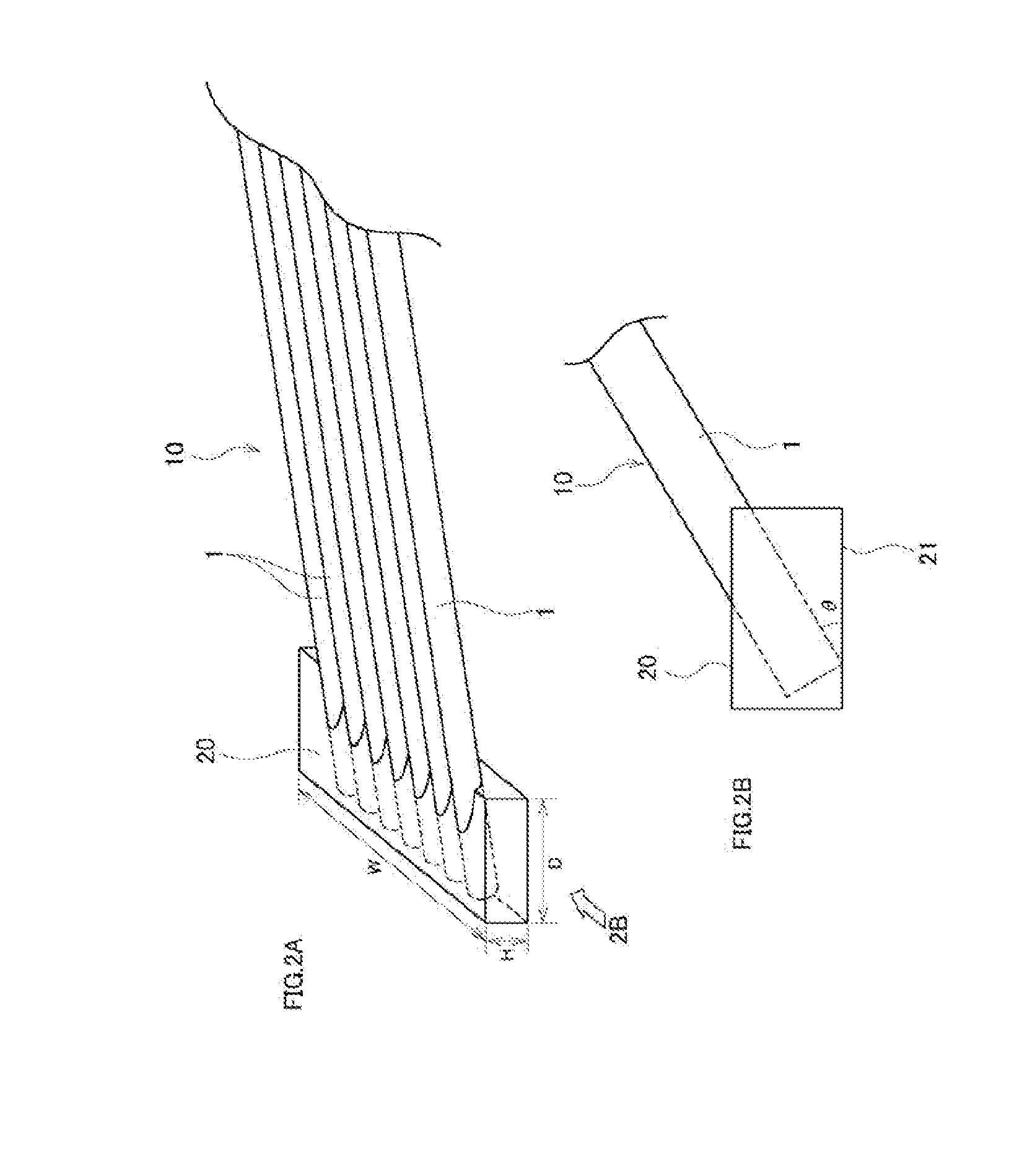
[0065]According to the aforementioned first embodiment, the cross sections of the coaxial cables 1 are formed into the inclined cross sections S1 inclined at a certain constant inclined angle, compared with a case in which the cross sections are vertically cut in the axial direction of the coaxial cables 1. However, in this second embodiment, the inclined angles within the inclined cross sections S2 of the coaxial cables 1 are not constant and varied.
[0066]According to the second embodiment, as illustrated in FIG. 7A, a jig 70 for fixing a plurality of coaxial cables 1 in a state of being arranged in parallel and curved, and as illustrated in FIG. 7B, the parts including curved parts of the coaxial cables 1 are removed to form the inclined cross sections S2.
[0067]The aforementioned jig 70 has, as illustrated in FIGS. 7A, 7B, or FIGS. 9A to 9C, a frame body 71 having a rectangular o...
PUM
Property
Measurement
Unit
Pressure
aaaaa
aaaaa
Dimension
aaaaa
aaaaa
Abstract
A multi-coaxial cableassembly of the present invention includes a multi-coaxial cable in which a plurality of coaxial cables having insulators, external conductors, and jackets on an outer periphery of center conductors are arranged in parallel; inclined cross sections formed on the end part of the multi-coaxial cable in such a manner as exposing the center conductors and the external conductors of the coaxial cables; and a wiring board or a connector having a wiring pattern to which the center conductors and the external conductors of the coaxial cables exposed on the inclined cross sections are directly connected.
Description
BACKGROUND[0001]1. Technical Field[0002]The present invention relates to a multi-coaxial cable assembly and a manufacturing method of the same, and further specifically relates to the multi-coaxial cable assembly capable of improving a connection structure / method between a plurality of coaxial cables of a multi-coaxial cable, and a wiring pattern of a wiring board or a connector.[0003]2. Description of Related Art[0004]As illustrated in FIG. 12, a conventional connection method of an superfine coaxial cable (superfine coaxial line) used in a medical device and an electronic device includes the steps of: stripping stepwise sequentially jackets 105, external conductors (shield lines) 104, and insulators 103 of a terminal of a plurality of superfine coaxial cables 101, and exposing the external conductors 104, the insulators 103, and center conductors 102 respectively, then parallely arranging these exposed plurality of coaxial cables 101, then connecting the exposed external conductor...
Claims
Application Information
Patent Timeline
Application Date:The date an application was filed.
Publication Date:The date a patent or application was officially published.
First Publication Date:The earliest publication date of a patent with the same application number.
Issue Date:Publication date of the patent grant document.
PCT Entry Date:The Entry date of PCT National Phase.
Estimated Expiry Date:The statutory expiry date of a patent right according to the Patent Law, and it is the longest term of protection that the patent right can achieve without the termination of the patent right due to other reasons(Term extension factor has been taken into account ).
Invalid Date:Actual expiry date is based on effective date or publication date of legal transaction data of invalid patent.

