Splitter with Multi-Stage Heat Pump Compressor and Inter-Reboiler

a heat pump compressor and splitter technology, applied in the direction of separation processes, distillation, organic chemistry, etc., can solve the problems of both energy and capital expenditure in propane/propylene separation by distillation, and achieve the effect of substantial energy savings

Inactive Publication Date: 2009-05-14
UOP LLC
View PDF45 Cites 38 Cited by
  • Summary
  • Abstract
  • Description
  • Claims
  • Application Information

AI Technical Summary

Benefits of technology

This patent describes a system that uses two heat pumps to improve efficiency when separating materials during manufacturing processes. By passing vapor from different parts of the process through specific heat exchangers, the temperature of each part can be increased while still maintaining high levels of purity. This leads to significant energy savings and allows for more flexible placement of equipment within the production line.

Problems solved by technology

This patent describes how traditional methods of producing light olefins involve cracking crude oil into lighter fractions using a variety of techniques including heat and pressure. However, these methods also result in large amounts of unwanted byproducts. To address this problem, researchers developed a method called fluidized catalytic cracking (FCC) which increases the yield of light olefins while reducing the amount of other compounds formed during the cracking process. Despite its benefits, current methods of separating and recovering individual light olefins from the mixture created by FCC require significant resources and technical expertise. Therefore, there is a need to develop new ways to efficiently extract pure light olefins without excessive energy usage.

Method used


Image

  • Splitter with Multi-Stage Heat Pump Compressor and Inter-Reboiler
  • Splitter with Multi-Stage Heat Pump Compressor and Inter-Reboiler
  • Splitter with Multi-Stage Heat Pump Compressor and Inter-Reboiler

Examples


Embodiment Construction

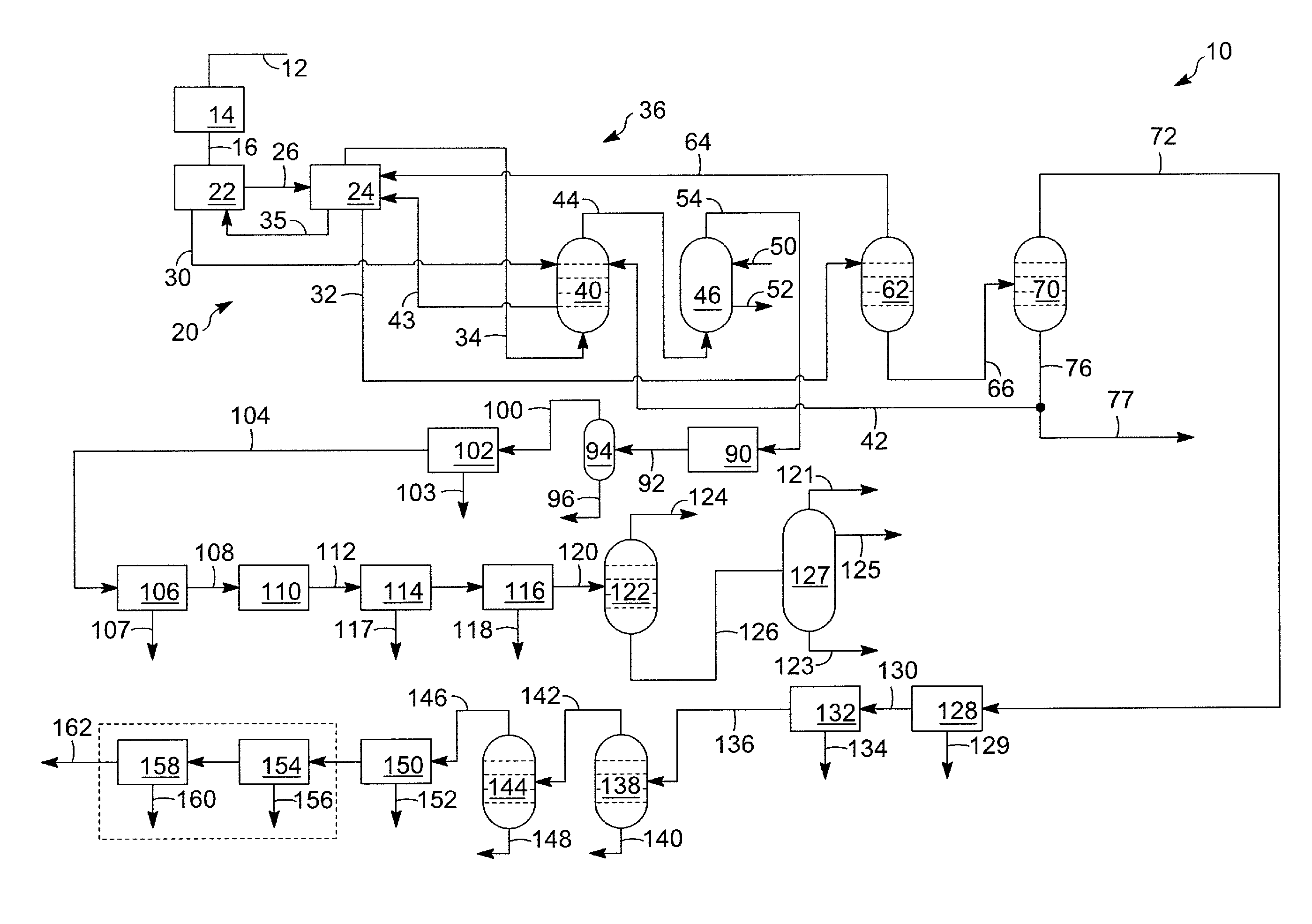
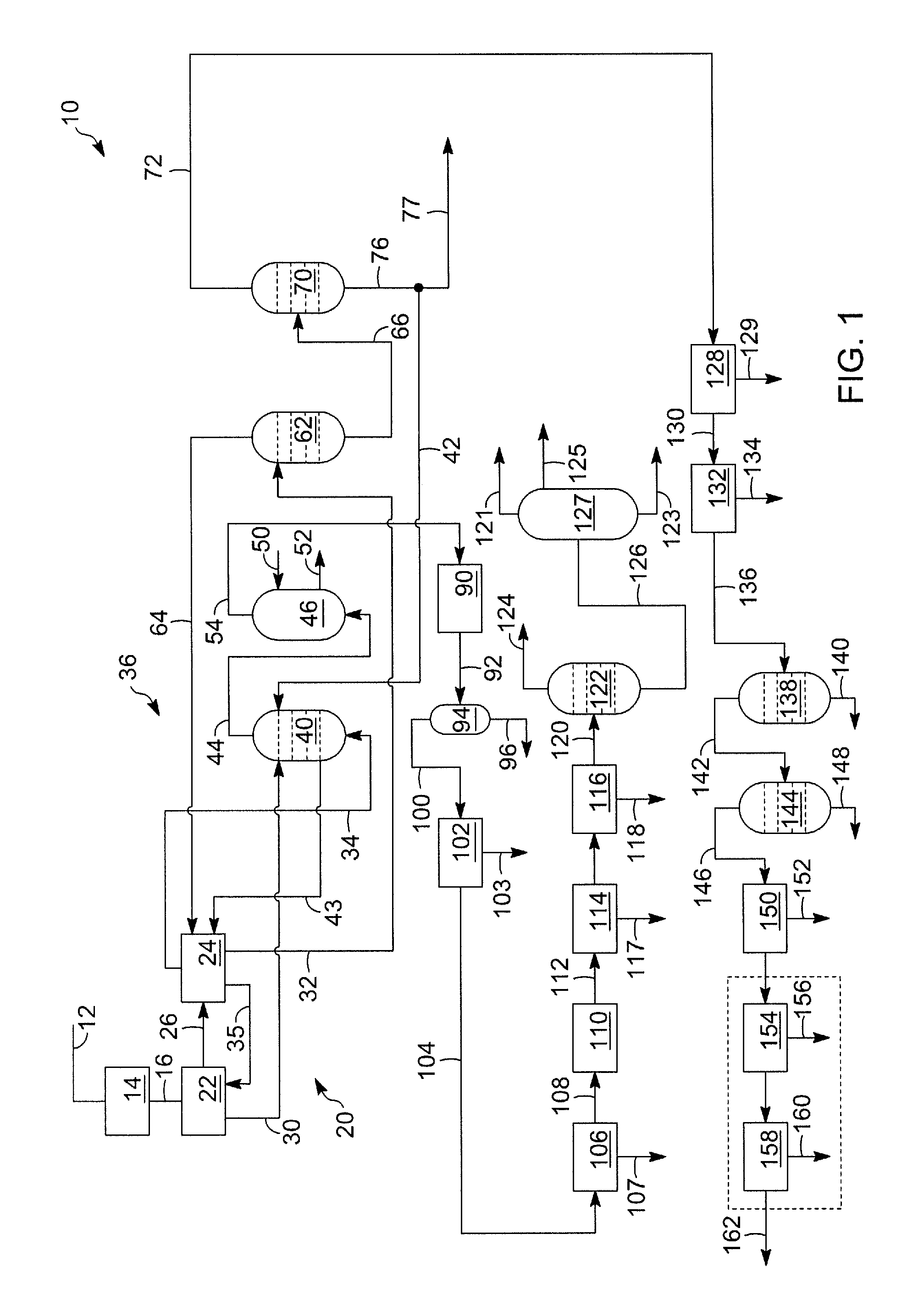
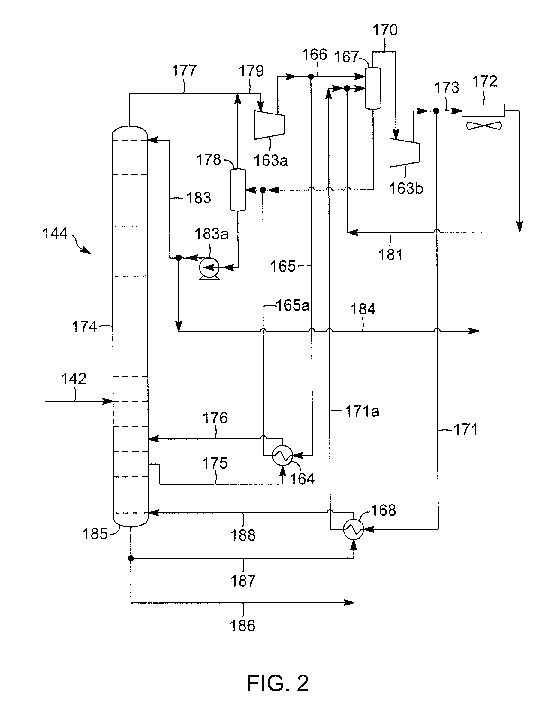
[0024]FIG. 1 schematically illustrates a system 10 for catalytic cracking a heavy hydrocarbon feedstock and obtaining light olefins via absorption-based product recovery and FIGS. 2 and 3 schematically illustrate splitter columns 144, 144a and system for separating two similar boiling point materials, e.g., a light olefin, such as propylene, from a mixture of the olefin and paraffin, such as a propylene / propane mixture. However, it will be noted again that the splitter systems of FIGS. 2 and 3 are not limited to a light olefin / paraffin or a propylene / propane separation.

[0025]The systems disclosed in FIGS. 2 and 3 are applicable to the separating of any two like-boiling point materials and are particularly useful for materials with a difference in boiling points of about 11° C. (˜20° F.) or less. Non-limiting examples of separations suitable for the systems 144, 144a of FIGS. 2 and 3 include: paraffin / olefin separations including ethane / ethylene, propane / propylene, butane / butylene, p...


PUM

PropertyMeasurementUnit
Fractionaaaaaaaaaa
Temperatureaaaaaaaaaa
Pressureaaaaaaaaaa

Abstract

A splitter system is disclosed that produces a product stream from a mixed stream of two materials with similar boiling points. A multi-stage heat pump compressor is used in combination with a bottoms reboiler and an intermediate reboiler resulting in reduced utility consumption. The appropriately placed intermediate reboiler enables use of a lower temperature heat source relative to the bottoms reboiler heat source. As a result, a lower pressure overhead vapor stream can be used to deliver heat to both the intermediate and bottoms reboilers, thereby conserving energy. The first stage of the multi-stage heat pump compressor delivers pressurized overhead vapor to the intermediate reboiler and the second stage provides pressurized overhead vapor to the bottoms reboiler. The disclosed design and method lessens the heat pump compressor power consumption and trim condenser duty for a propylene/propane splitter system by over 20%. A third stage of compression upstream of the overhead trim condenser may be used for purposes of making the column pressure and temperatures independent of the trim condenser temperature.

Description


Claims


Application Information

Patent Timeline
Owner UOP LLC
Why Eureka
Try Eureka