Cool double-effect lithium bromide spray absorption type refrigeration cycle system

An absorption refrigeration and circulation system technology, applied in refrigerators, refrigeration components, refrigeration and liquefaction, etc., can solve the problems that the condensation pressure and condensation temperature cannot be increased independently, and cannot meet the application conditions of lithium bromide, etc.

Active Publication Date: 2014-12-03
HARBIN INST OF TECH
View PDF6 Cites 4 Cited by
  • Summary
  • Abstract
  • Description
  • Claims
  • Application Information

AI Technical Summary

Problems solved by technology

[0005] The present invention solves the problem that the outlet temperature of the saturated dilute solution of the second absorber 5 and the temperature of the first cooling heat source 26 are low during the operation of the traditional lithium bromide absorption refrigeration cycle system, so that the higher temperature of the...

Method used


Image

  • Cool double-effect lithium bromide spray absorption type refrigeration cycle system
  • Cool double-effect lithium bromide spray absorption type refrigeration cycle system
  • Cool double-effect lithium bromide spray absorption type refrigeration cycle system

Examples


specific Embodiment approach 1

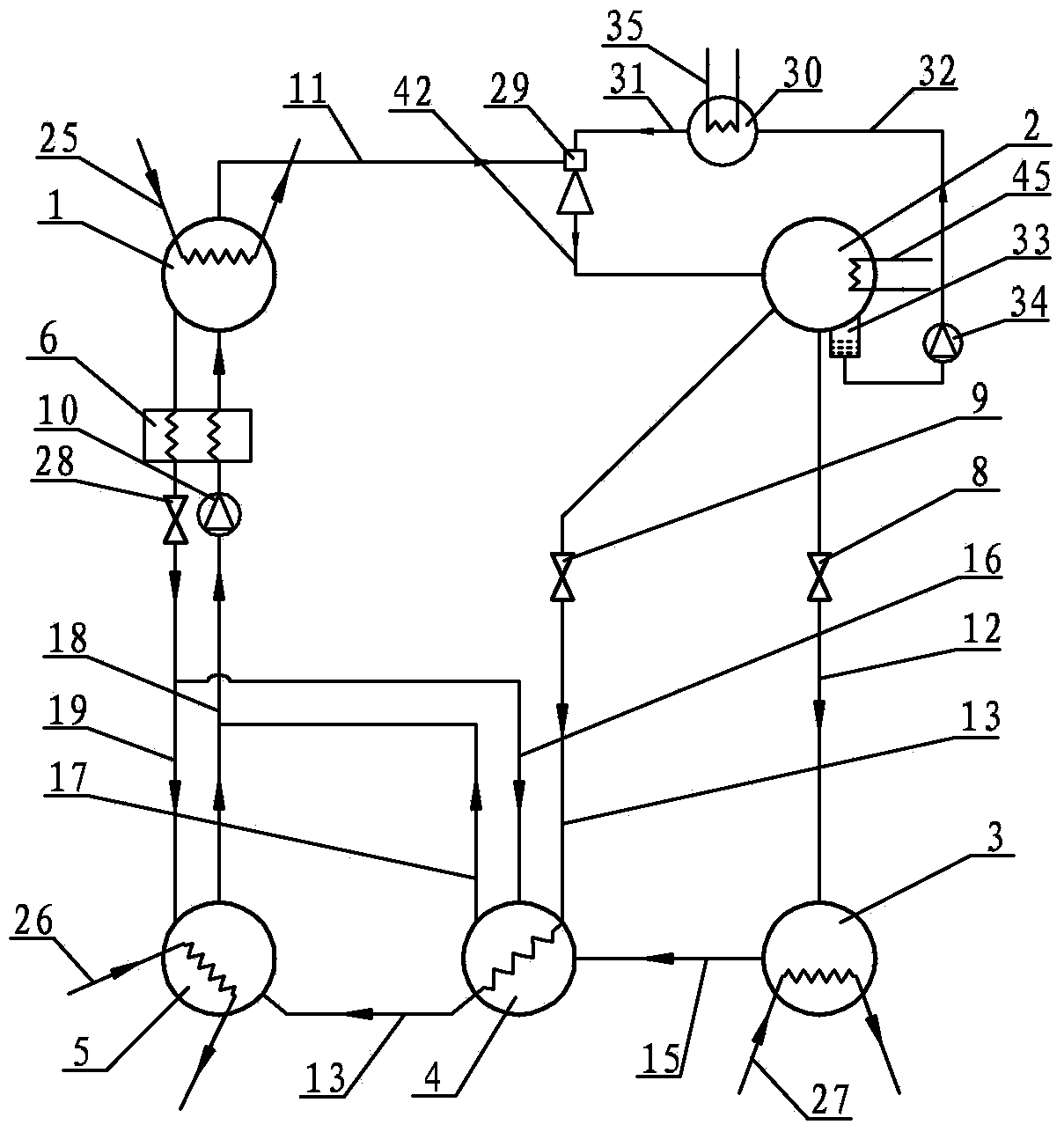
[0032] Specific implementation mode one: combine figure 1 Describe this embodiment, this embodiment includes a generator 1, a condenser 2, an evaporator 3, a first absorber 4, a second absorber 5, a solution heat exchanger 6, a first throttling expansion device 8, a second section Flow expansion device 9, first solution pump 10, first refrigerant water vapor pipeline 11, first refrigerant water passage 12, second refrigerant water passage 13, second refrigerant water vapor pipeline 15, second rich Solution pipeline 16, second dilute solution pipeline 17, first dilute solution pipeline 18, first concentrated solution pipeline 19, throttle valve 28, injector 29, boiler 30, first connecting pipe 31, second The connecting pipe 32, the liquid storage device 33, the refrigerant water pump 34 and the third connecting pipe 42, the refrigerant water passage of the condenser 2 is divided into three paths, one of which: the condenser 2 passes through the first refrigerant water passage ...

specific Embodiment approach 2

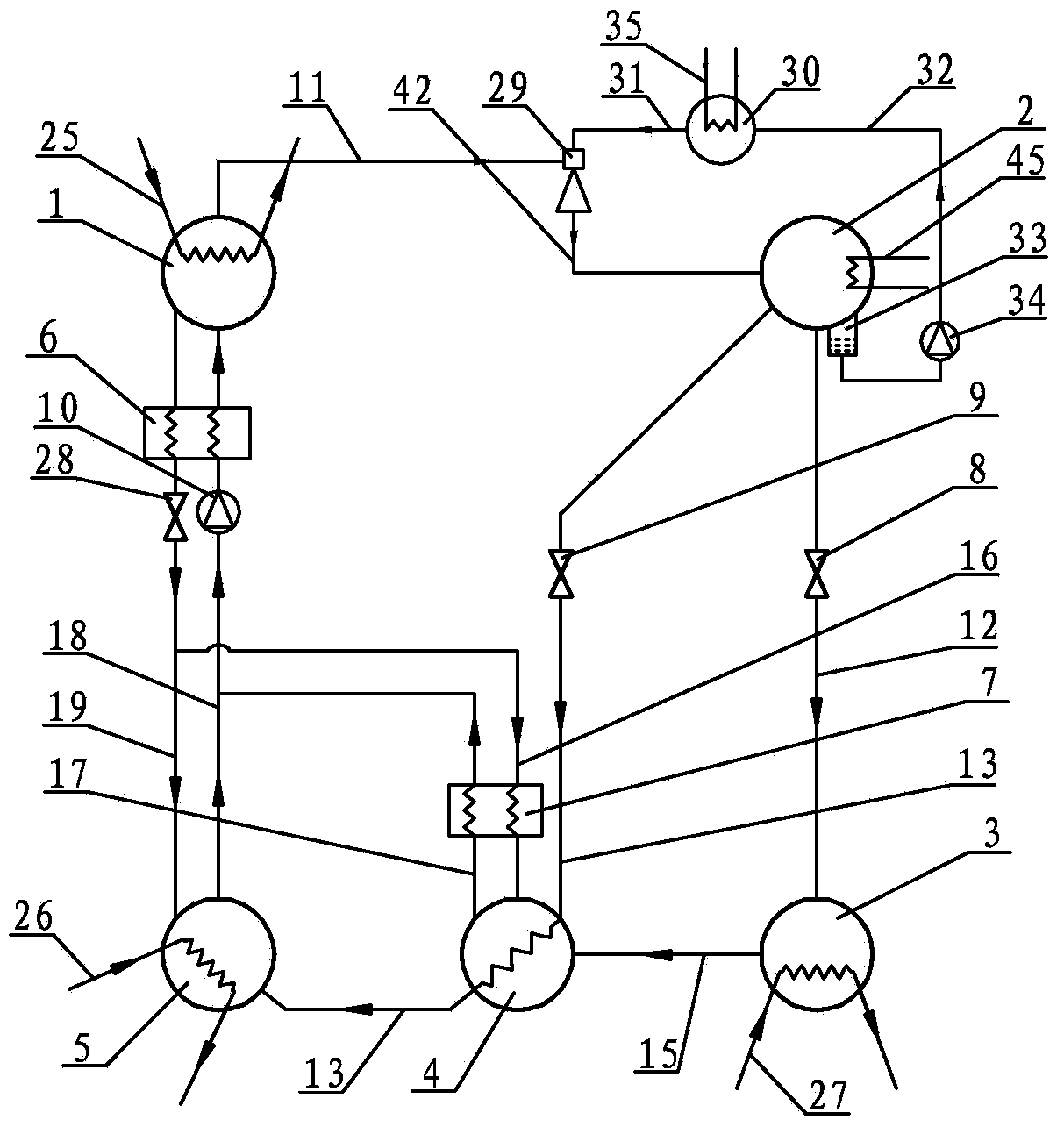
[0038] Specific implementation mode two: combination figure 2 Describe this embodiment, the difference between this embodiment and specific embodiment one is that it also adds a second solution heat exchanger 7, and the second solution heat exchanger 7 is arranged on the second concentrated solution pipeline 16 and the second dilute solution pipe on road 17. The second solution heat exchanger 7 enables heat exchange between the concentrated and dilute solutions flowing into and out of the first absorber 4, thereby improving the efficiency of the refrigeration cycle. Other components and connections are the same as those in the first embodiment.

specific Embodiment approach 3

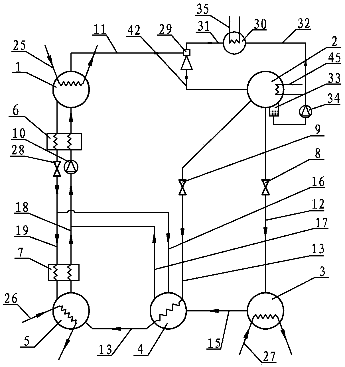
[0039] Specific implementation mode three: combination image 3 Describe this embodiment, the difference between this embodiment and specific embodiment 1 is that it also adds a second solution heat exchanger 7, and the second solution heat exchanger 7 is located between the second dilute solution pipeline 17 and the second absorber 5 Between, and the second solution heat exchanger 7 is arranged on the first dilute solution pipeline 18 and the first concentrated solution pipeline 19 . The second solution heat exchanger 7 enables heat exchange between the concentrated and dilute solutions flowing into and out of the second absorber 5, thereby improving the efficiency of the refrigeration cycle. Other components and connections are the same as those in the second embodiment.


PUM


Abstract

The invention relates to a cool double-effect lithium bromide spray absorption type refrigeration cycle system. A refrigerant water passage of a condenser is divided into three paths; in the first path, the condenser is communicated with an evaporator; in the second path, one end of the second refrigerant water passage is communicated with the condenser, and the other end of the second refrigerant water passage passes through a first absorber to be communicated with a second absorber; in the third path, a liquid storage device is communicated with the condenser, one end of a second connecting pipe is communicated with the liquid storage device, the other end of the second connecting pipe is communicated with a boiler, one end of a first connecting pipe is communicated with a boiler, the other end of the first connecting pipe is communicated with the condenser, the other end of the connecting pipe is communicated with an ejector, one end of a first refrigerant water vapor pipeline is communicated with the ejector, the other end of the first refrigerant water vapor pipeline is communicated with a generator, the first absorber is communicated with an evaporator, one end of a medium concentration solution pipeline is communicated with the first absorber, the other end of the medium concentration solution pipeline is communicated with the second absorber, one end of a first dilute solution pipeline and one end of a first concentrated solution pipeline are both communicated with the second absorber, and the other ends of the first dilute solution pipeline and the first concentrated solution pipeline are both communicated with the generator. The system is used in an absorption type water source heat pump system.

Description

technical field [0001] The invention relates to an absorption refrigeration cycle system, in particular to a cold double-effect lithium bromide injection absorption refrigeration cycle system. Background technique [0002] Traditional absorption refrigeration cycle systems such as Figure 12 As shown, it is mainly composed of a generator 1, a condenser 2, an evaporator 3, a second absorber 5, a solution heat exchanger 6, a first solution pump 10 and connected pipelines. Under the action of an external heat source, the generator 1 concentrates the lithium bromide solution in it to generate high-temperature and high-pressure refrigerant water vapor, which enters the condenser 2 through the first refrigerant water vapor pipeline 11 to condense, and the condensed low-temperature The refrigerant water enters the evaporator 3 through the first refrigerant water channel 12 after throttling and depressurizing through the first throttling expansion device 8, and in the evaporator 3, ...

Claims


Application Information

Patent Timeline
IPC IPC(8): F25B25/00F25B41/00F25B41/42
Inventor 张承虎李亚平闫艳艳
Owner HARBIN INST OF TECH
Why Eureka
Try Eureka