Fuel injector filter

a fuel injector and filter technology, applied in the field of filters, can solve the problems of inability to meet the needs of injection events, and wear of the close tolerance of the injector components, so as to achieve the effect of preventing the slipping of debris particles with high aspect ratios, and preventing the slipping of debris particles

Inactive Publication Date: 2009-05-14
ROBERT BOSCH GMBH
View PDF12 Cites 18 Cited by
  • Summary
  • Abstract
  • Description
  • Claims
  • Application Information

AI Technical Summary

Problems solved by technology

Debris in the fuel flow can not only obstruct the nozzle and cause unacceptable injector performance, but over time, wear at the close tolerances of the injector components.
A problem with known edge filters is that debris particles with high aspect ratios can still slip through and interfere with injection events.
Reducing the gap size may cause an unacceptable flow restriction, and may still not solve the problem of high aspect ratio particles.

Method used


Image

  • Fuel injector filter
  • Fuel injector filter
  • Fuel injector filter

Examples


first embodiment

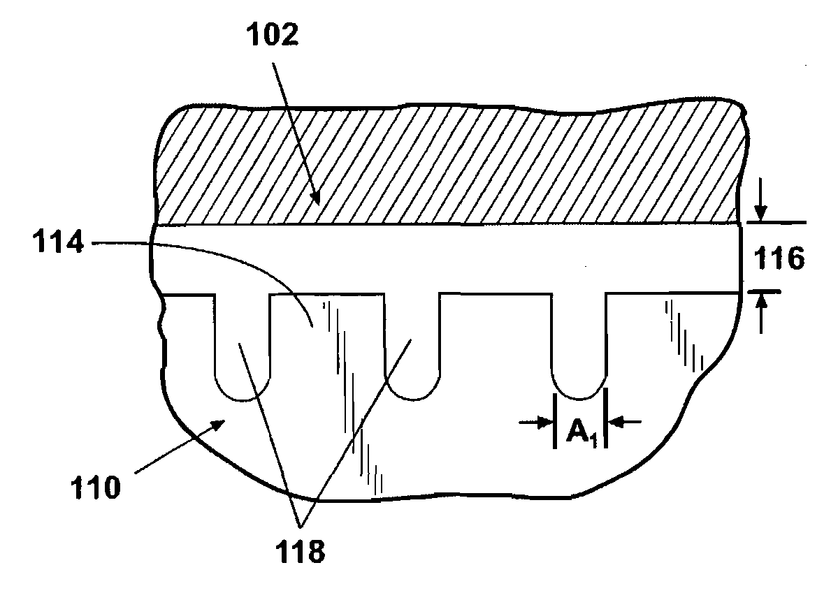
[0025]Looking first at FIGS. 3 and 4, the invention is illustrated in an edge filter 100 adapted to be mounted in a high pressure conduit 102. The edge filter 100 has an inlet end 104, a filter section 106, and an outlet end 108. The filter section 106 extends between the inlet end 104 and the outlet end 108. A plurality of inlet channels 110 (equidistant from each other) extend longitudinally from the inlet end 104 and terminate before they reach the outlet end 108. As illustrated, three inlet channels 110 extend through the inlet end 104. Similarly, a plurality of outlet channels 112 interspersed between the inlet channels 110 extend longitudinally from the outlet end 108 and terminate before they reach the inlet end 104. The outlet channels 112 extend through the outlet end 108. Here, there are three outlet channels 110. The inlet and outlet channels 110, 112 are separated from each other by ridges 114 which are in the filter section 106.

[0026]The diameter D of the edge filter 10...

second embodiment

[0029]Looking now at FIGS. 5 and 6, the invention is illustrated in a sack filter 200 mounted in a high pressure conduit 202. The sack filter 200 is formed from a cylinder having an inlet section 204, a filter section 206, and an end section 208. The inlet section 204 has a diameter D larger than the diameter d of the filter section 206. The filter section 206 comprises a plurality of holes 210 extending through the wall, preferably laser drilled in a range of approximately 10-21 holes / mm2. Each hole has a diameter of about 50 microns. The material is preferably stainless steel. The end section 208 is closed by crimping to create a blind sack 211, preferably closed in that it has no holes to provide an exit. The blind sack 211 is that volume of the sack filter more than about 1 mm beyond the last hole 210 downstream from the inlet section 204.

[0030]The diameter D of the inlet section 204 is the same as (or nominally larger than) the inside diameter of the high pressure conduit 202. ...


PUM

PropertyMeasurementUnit
pressure gradientaaaaaaaaaa
diameteraaaaaaaaaa
pressureaaaaaaaaaa

Abstract

A filter (100, 200) is provided especially for high aspect ratio particles in a conduit (102, 202) for a fuel injection system. The filter (100, 200) can be an edge filter (100) or a sack filter (200) with an annular gap (116, 212) between the filter section (106, 206) and the conduit wall sized smaller than previously known in order to filter high aspect ratio particles without significant changes in pressure drop. The edge filter (100) relates the gap (116) to grooves (118) in the filter section (106), and the sack filter (200) relates the gap (212) to the size of the holes (210) in the filter section (206).

Description

BACKGROUND OF THE INVENTION[0001]1. Field of the Invention[0002]The present invention relates to filters for a common rail fuel system and more particularly, filters that are utilized in high pressure inlets to fuel injectors.[0003]2. Description of the Related Art[0004]Common rail fuel systems are well known for high pressure fuel injection in internal combustion engines. Pressures in common rail systems can range from 250 bar to 2200 bar (3,600 to 32,000 psi). Individual injectors are connected to the common rail by high pressure conduits. Common rail fuel systems utilize electronic controls to control the timing of the beginning of injection and the completion of injection. The timing of the injection cycle may be adjusted electronically. Maintaining close tolerances of the injector components in a high pressure environment is important because it maintains the accuracy of fuel injection events. Debris in the fuel flow can not only obstruct the nozzle and cause unacceptable injec...

Claims


Application Information

Patent Timeline
Patent Type & Authority Applications(United States)
IPC IPC(8): B01D29/07F02M37/32
CPCB01D29/35F02M37/22F02M61/165B01D29/44F02M37/32
Inventor HARKEMA, RANDALL C.BENNETT, JOSHVANDER WEIDE, DEREK
Owner ROBERT BOSCH GMBH
Why Eureka
Try Eureka