Optics element and method for detecting detachment state of chromatic probe detachment sensor system

A distance measuring sensor, optical element technology, applied in the field of detachment sensing, which can solve problems such as detector, coordinate measuring machine and/or workpiece damage

Active Publication Date: 2015-01-14
MITUTOYO CORP
View PDF12 Cites 18 Cited by
  • Summary
  • Abstract
  • Description
  • Claims
  • Application Information

AI Technical Summary

Problems solved by technology

These collisions can cause damage to the detector, CMM and / or workpiece

Method used


Image

  • Optics element and method for detecting detachment state of chromatic probe detachment sensor system
  • Optics element and method for detecting detachment state of chromatic probe detachment sensor system
  • Optics element and method for detecting detachment state of chromatic probe detachment sensor system

Examples


Embodiment Construction

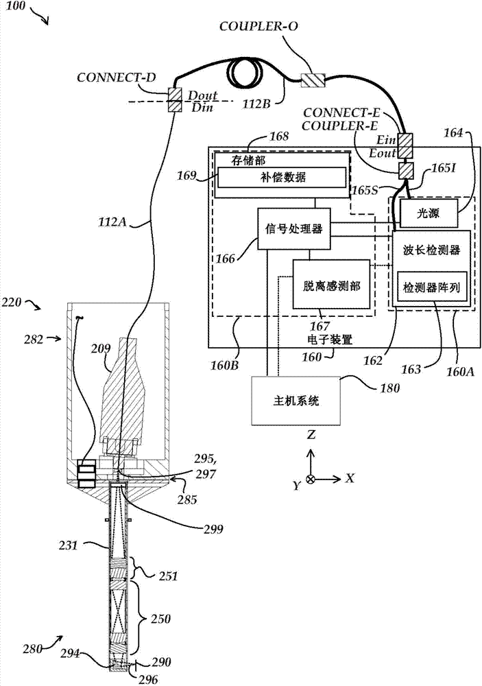
[0028] figure 1is a block diagram of a first exemplary chromatic range sensor (CRS) system 100 based on the operating principles expected to be employed in conjunction with a coordinate measuring machine (CMM). The CRS system 100 has certain similarities to the sensors described in US Patent 7,876,456 and US Patent 7,990,522 (the '456 patent and the '522 patent, respectively), the contents of which are hereby incorporated by reference in their entirety. like figure 1 As shown, the CRS system 100 includes an electronic part 160 and an optical pen 220 . It should be understood that figure 1 The illustrated CRS system 100 is a chromatographic point sensor system that measures one measurement point at a time. figure 1 The illustrated optical pen 220 is an optical pen. However, in various embodiments, alternative types of chromatographic ranging systems, such as chromatic line sensors, may be configured to operate in accordance with the systems and methods disclosed herein. Op...


PUM


Abstract

A system and method for a chromatic probe detachment sensor is provided. A detachment signal element is included in an interchangeable optics element of a probe. The detachment signal element is configured to substantially transmit a first set of wavelengths corresponding to a measuring range, and at least partially reflect a set of detachment element wavelengths. In one implementation, the detachment signal element comprises a thin film coating such as a sharp edge filter. The detection of a detachment condition can thus be achieved using the existing probe electronics without requiring the addition of other external sensors or wiring to the probe or coordinate measuring machine that utilizes the probe. The sensing of a detachment condition may be utilized to halt further movement of the probe to minimize damage in the event of a collision.

Description

technical field [0001] The present application relates generally to precision measuring instruments, and more particularly to disengagement sensing methods such as may be used in conjunction with chromatic range sensor probe systems for coordinate measuring machines. Background technique [0002] In various types of coordinate measuring machines, probes may be utilized to sense points on the surface of a workpiece. In one type of probe, the workpiece is measured directly by bringing the probe's mechanical contacts into contact with points along the surface of the workpiece. In some cases, the mechanical contacts are balls. Some coordinate measuring machines use both optical and mechanical measurement sensors. These devices are described in US Patent 4,908,951 and US Patent 5,825,666, the entire contents of which patents are hereby incorporated by reference. Also disclosed is an automatic changing rack for holding a plurality of detectors, detector holders, lenses selectiv...

Claims


Application Information

Patent Timeline
Patent Type & Authority Applications(China)
IPC IPC(8): G01B11/00
CPCG01B11/14G01B11/007G01B2210/50
Inventor 大卫·威廉·赛思克
Owner MITUTOYO CORP
Why Eureka
Try Eureka