Vibration-Reduction Fan Driving Circuit
- Summary
- Abstract
- Description
- Claims
- Application Information
AI Technical Summary
Benefits of technology
Problems solved by technology
Method used
Image
Examples
Embodiment Construction
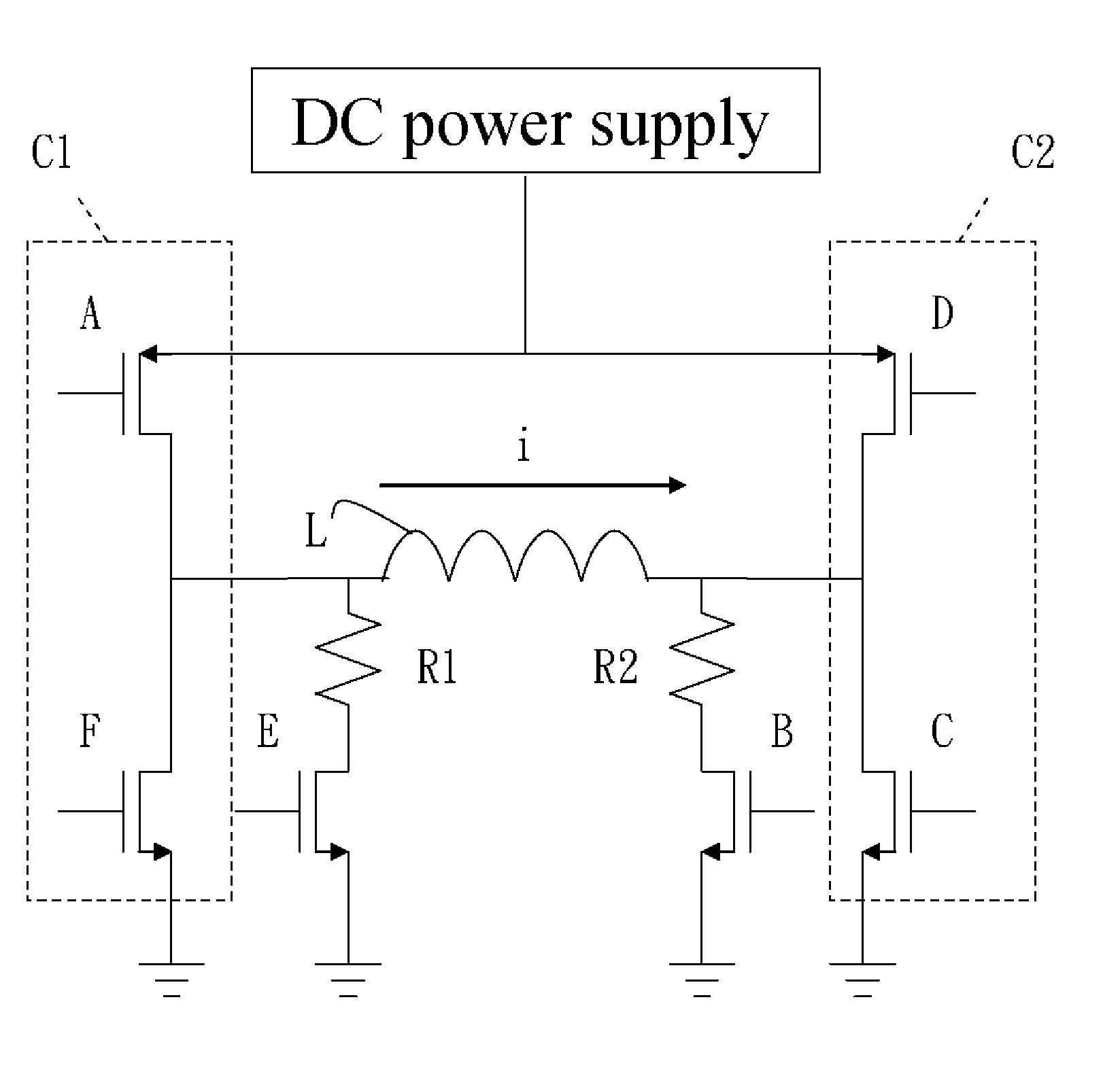
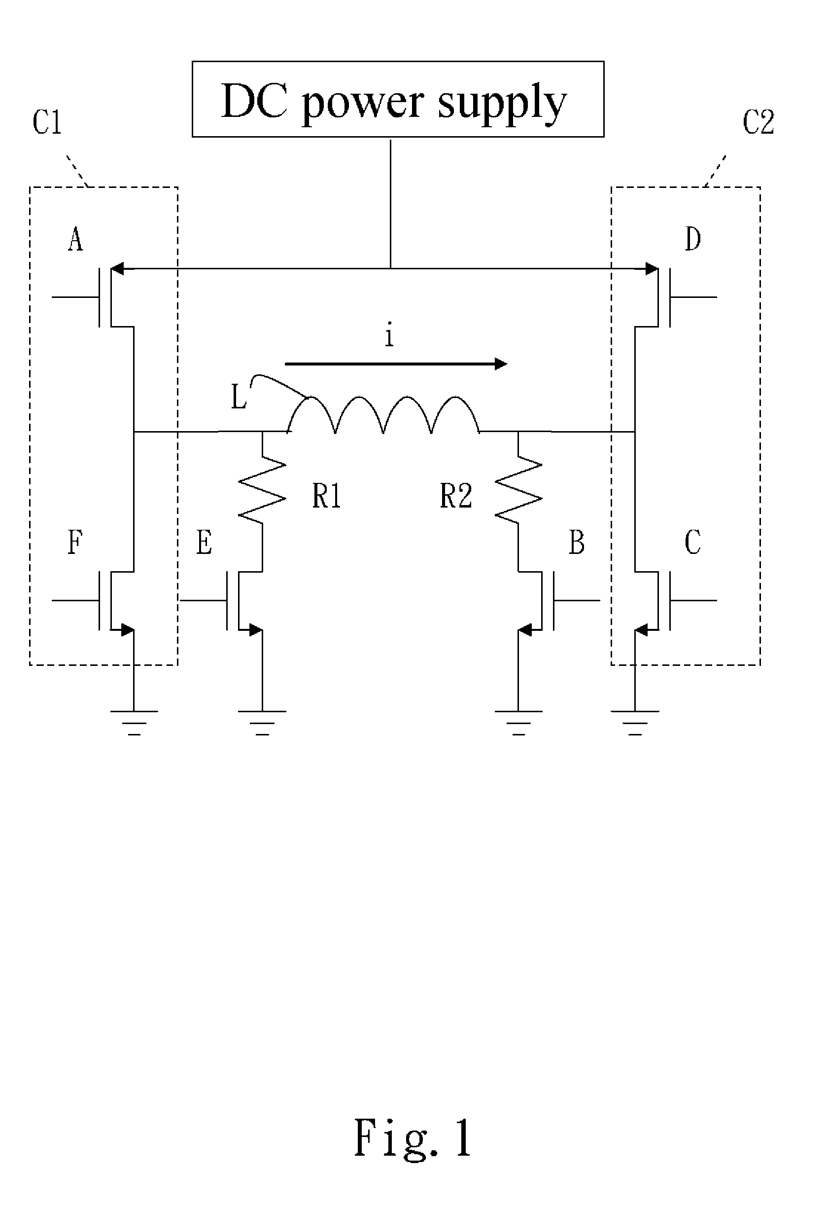
[0015]Please refer to FIG. 1 that is a schematic circuit diagram of a vibration-reduction fan driving circuit according to a first preferred embodiment of the present invention. The vibration-reduction fan driving circuit of the present invention maybe applied to fan L that operates according to an electric current signal sent thereto. In FIG. 1, the fan L is represented by a magnetic induction coil thereof.
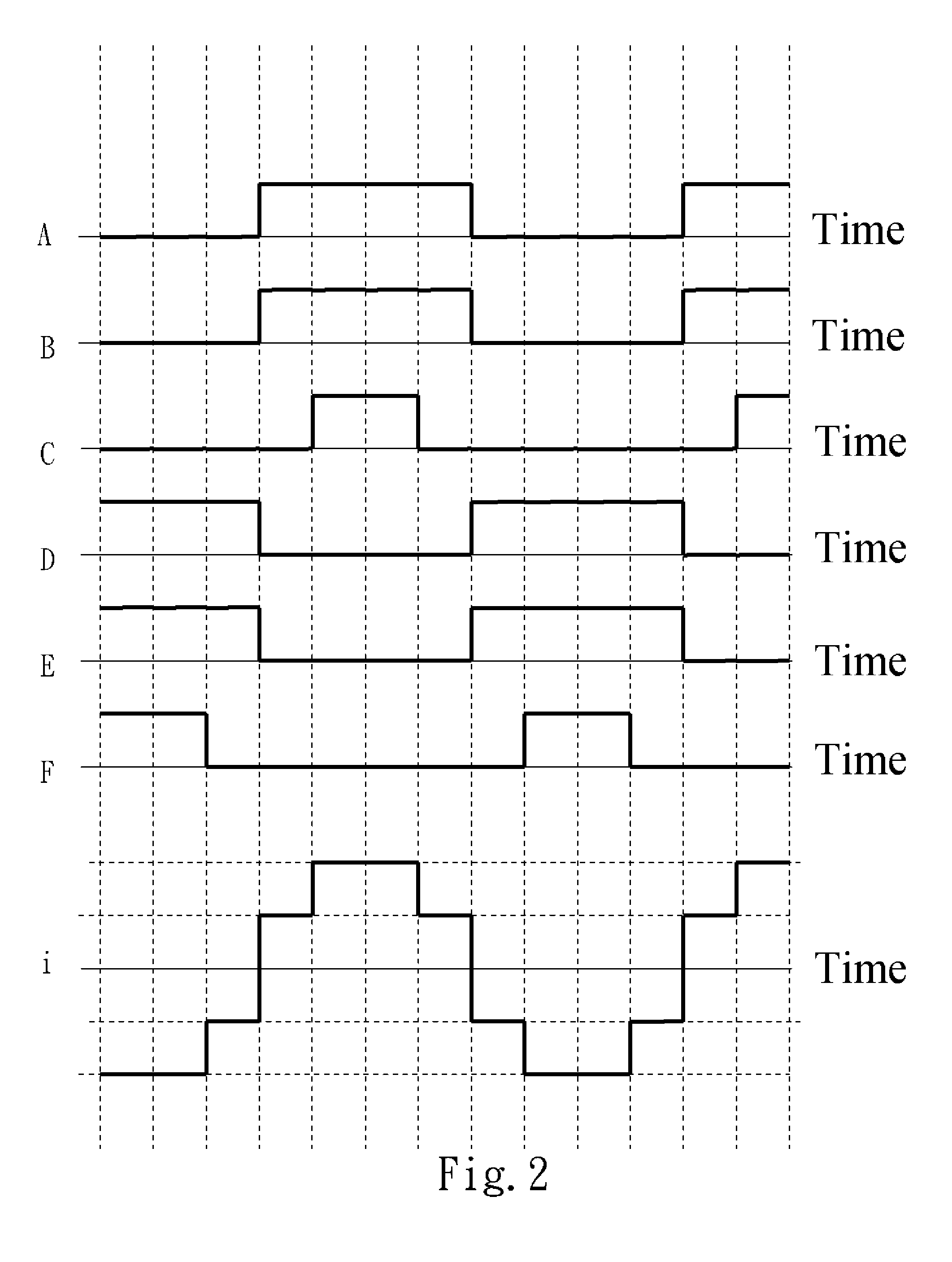
[0016]The vibration-reduction fan driving circuit of the present invention is characterized in a current buffer unit connected to a drive current supplied from a power source and having a relatively large magnitude of change in current. The current buffer unit divides the original drive current into multiple continuously changing drive currents that have a relatively small magnitude of change in current, so that electric current supplied to the fan is regulated and output fractionally to achieve the purpose of reducing the vibration of fan caused by a large magnitude of change in...
PUM
 Abstract
Description
Claims
Application Information
 - R&D
- Intellectual Property
- Life Sciences
- Materials
- Tech Scout
- Unparalleled Data Quality
- Higher Quality Content
- 60% Fewer Hallucinations
Browse by: Latest US Patents, China's latest patents, Technical Efficacy Thesaurus, Application Domain, Technology Topic, Popular Technical Reports.
© 2025 PatSnap. All rights reserved.Legal|Privacy policy|Modern Slavery Act Transparency Statement|Sitemap|About US| Contact US: help@patsnap.com


