
Line Head and Image Forming Apparatus Incorporating the Same

a technology of image forming apparatus and line head, which is applied in the field of line head, can solve the problems of inability to deal with image quality deterioration, no suggestion of a solution to the lowering of emitted light amount, etc., and achieve the effect of no deterioration in image quality

Inactive Publication Date: 2009-05-14
SEIKO EPSON CORP
View PDF23 Cites 5 Cited by
  • Summary
  • Abstract
  • Description
  • Claims
  • Application Information

AI Technical Summary

Benefits of technology

The invention provides a line head and an image forming apparatus that can prevent image quality degradation even when the operating time period exceeds a predetermined time period. This is achieved by compensating for the deterioration of the organic electroluminescence elements used in the line head through a constant current control. The line head includes at least one light emission array with a plurality of light emitting elements arranged in a first direction, and a monitor that quantitatively monitors the light emitting state of at least one of the light emitting elements. A controller performs a constant current control with respect to each of the light emitting elements based on the monitored amount. This compensates for the lowering of the emitted light amount from the light emitting devices caused by aged deterioration. The image forming apparatus includes an image carrier and a developing device that supplies developer onto the photoconductive surface to make the electrostatic latent image visible.

Problems solved by technology

However, there is no suggestion about a solution to the lowering of the emitted light amount when the operating time period exceeds a predetermined value as shown in FIGS. 17A and 17B in the case where organic EL elements are controlled by constant voltage control.
Therefore, when organic EL elements attached to a line head are driven by constant voltage control, there is a problem that the technique cannot deal with deterioration in image quality caused by the lowering of the emitted light amount when the operating time period exceeds the predetermined value.

Method used


Image

  • Line Head and Image Forming Apparatus Incorporating the Same
  • Line Head and Image Forming Apparatus Incorporating the Same
  • Line Head and Image Forming Apparatus Incorporating the Same

Examples


first embodiment

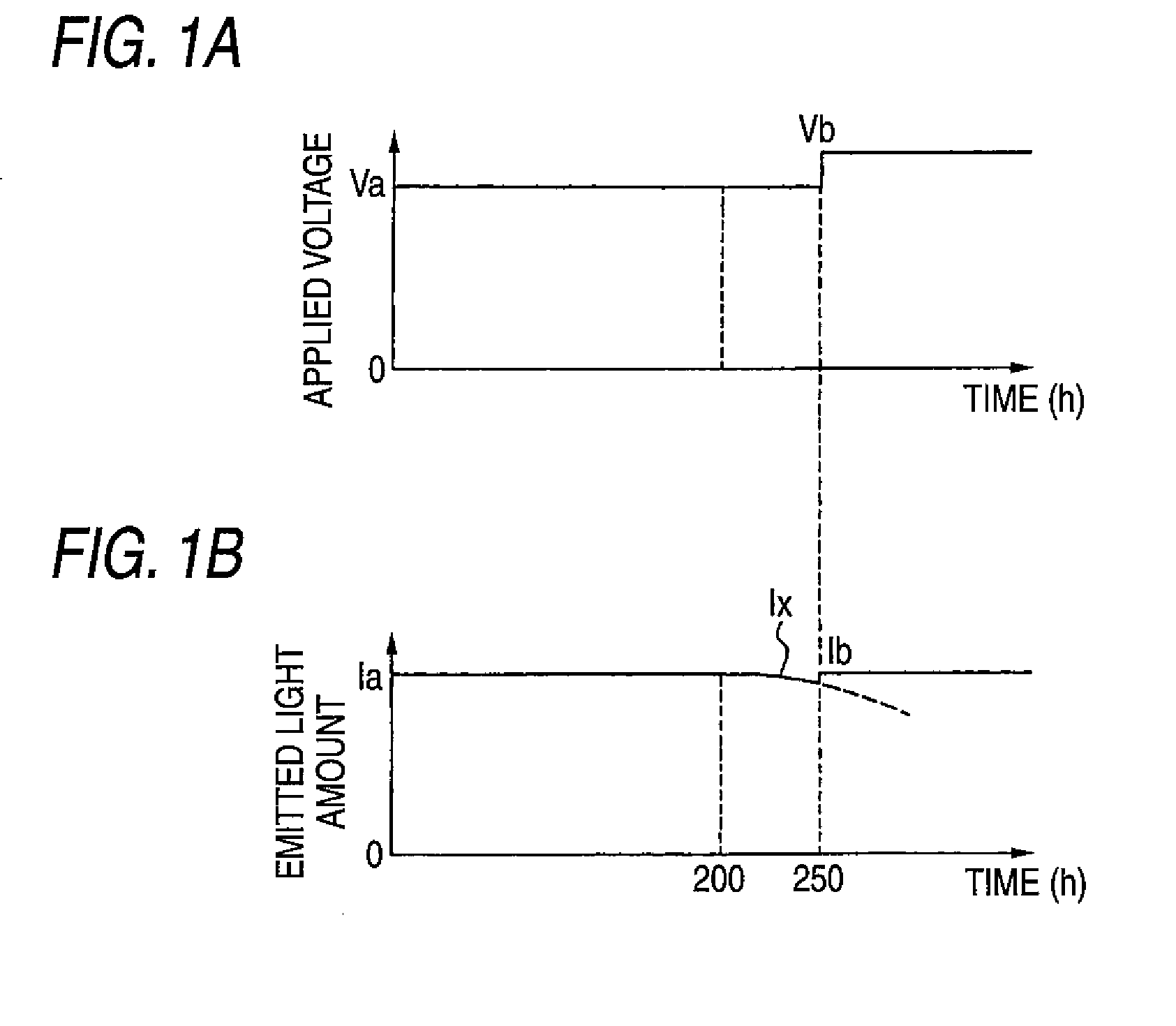
[0085]FIGS. 1A and 1B show an operation principle of a line head according to the invention. In this embodiment, constant voltage control is performed on light emitting elements with a voltage whose value is increased as soon as the operating time period of each light emitting element exceeds a predetermined time period, for example, 250 hours. The lowered emitted light amount is increased by such a constant voltage control to be restored to its initial emitted light amount.

[0086]FIG. 1A shows the relationship between the operating time period of each light emitting element and the voltage value applied to the light emitting element. In this example, a constant voltage Va is initially applied to the light emitting element so as to perform constant voltage control thereon. As soon as the operating time period of the light emitting element exceeds 250 hours, the driving voltage is increased from the value Va to a value Vb, with which constant voltage control is performed on the light ...

fourth embodiment

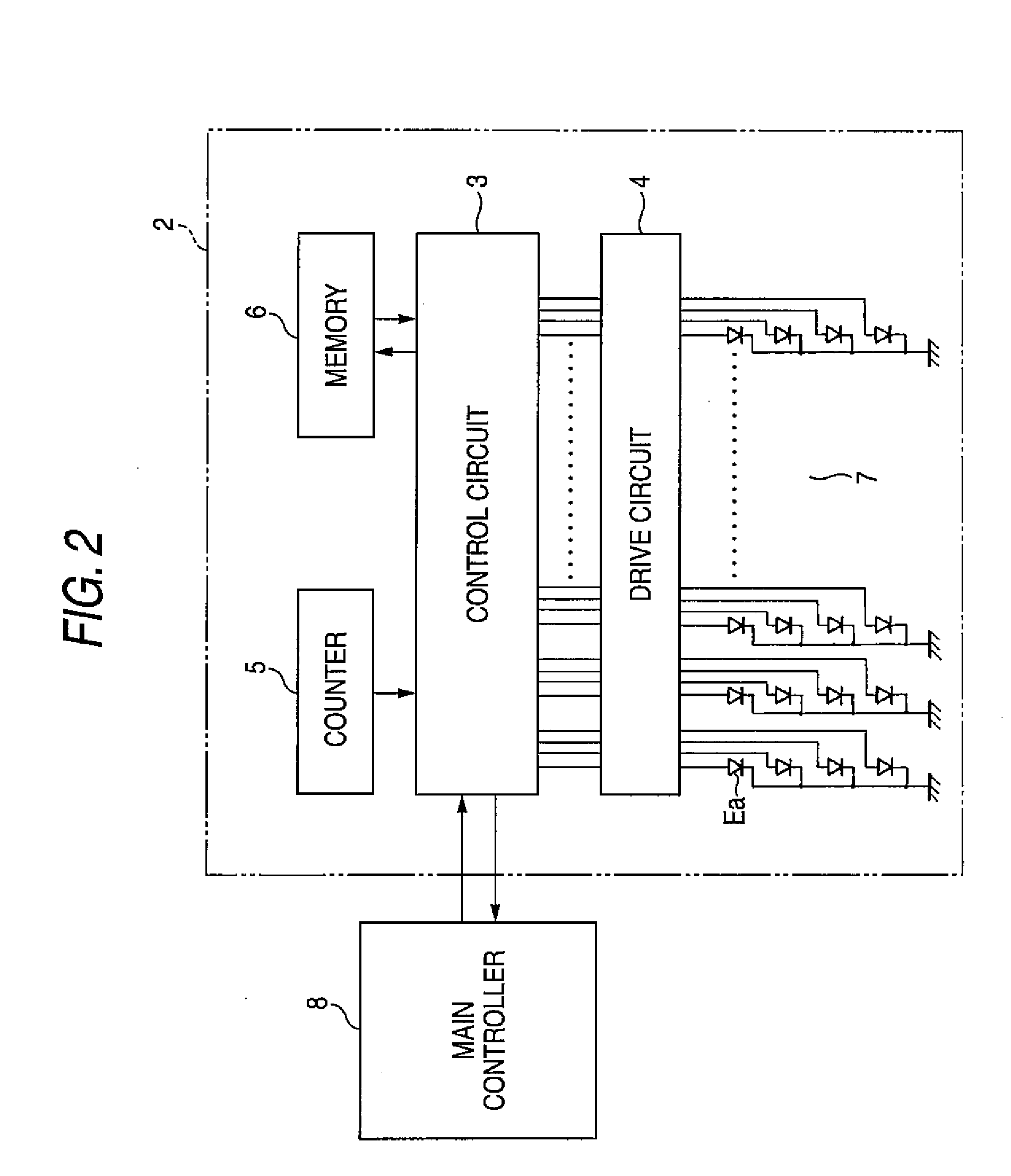
[0137]When each light emitting element is to be driven, the control circuit 3 reads the aforementioned relationship data from the memory 6, and compares this with the measurement signal from the light amount sensor 9. When the operating time of the light emitting element exceeds 200 hours, a value measured by the light amount sensor 9 decreases along the characteristic Ix in FIG. 9C. When the operating time of the light emitting element is accumulated to reach 250 hours, the amount of light emission decreases to the value Iy. In this event, the control circuit 3 increases the driving current from the value Ia to the value Ib so as to perform constant current control upon each light emitting element in the same manner as in the That is, the light emission amount Iy when the operating time reaches 250 hours serves as a reference value for determining whether to increase the driving current from the value Fa to the value Fb or not.

[0138]The constant current control describe the above ...


PUM


Abstract

At least one light emission array includes a plurality of light emitting elements arrayed in a first direction. Each of the light emitting elements is an organic electroluminescence element. A monitor quantitatively monitors a light emitting state of at least one of the light emitting elements to obtain a monitored amount. A comparator compares the monitored amount and a reference amount. A controller performs a constant current control with respect to at least one of the light emitting elements in accordance with a result of the comparison performed by the comparator.

Description

BACKGROUND OF THE INVENTION[0001]The present invention relates to a line head using organic EL (electroluminescence) elements and an image forming apparatus incorporating such a line head.[0002]There has been developed image forming apparatus in which a line head having a large number of arrayed light emitting devices is used as an exposure unit. Japanese Patent Publication No. 11-138899A discloses an image forming apparatus in which a light emitting device array made of a plurality of light emitting devices is integrated in a single chip so as to form an exposure unit. In this example, single-chip light emitting device arrays for respective colors are once formed on a single substrate and then separated. The single-chip light emitting device arrays are disposed in corresponding color developing units respectively. Thus, the variation in light emitting characteristic is canceled.[0003]In addition to light emission diodes (LEDs), organic EL elements have been proposed as light emitti...

Claims


Application Information

Patent Timeline
Patent Type & Authority Applications(United States)
IPC IPC(8): B41J2/45B41J2/447G06K15/12
CPCB41J2/45G06K15/1247G06K15/1214
Inventor TSUJINO, KIYOSHINOMURA, YUJIROIKUMA, KEN
Owner SEIKO EPSON CORP
Learn More