Image forming apparatus

a technology of image forming apparatus and forming plate, which is applied in the direction of electrographic process apparatus, instruments, optics, etc., can solve the problems of deformation of image forming and sheet transport performance when operated, high manufacturing cost and structural complexity, and the displacement of images produced

Inactive Publication Date: 2009-05-14
RICOH KK
View PDF7 Cites 115 Cited by
  • Summary
  • Abstract
  • Description
  • Claims
  • Application Information

AI Technical Summary

Problems solved by technology

Misalignment of the transfer nip and the fixing nip results in displacement of images produced in the transfer and fixing processes, or curling and wrinkling of recording sheets traveling along the nip-to-nip path.
In order for the two devices to work properly in conjunction with each other, the conventional design requires dimensional control wi

Method used


Image

  • Image forming apparatus
  • Image forming apparatus
  • Image forming apparatus

Examples


Embodiment Construction

[0019]In describing exemplary embodiments illustrated in the drawings, specific terminology is employed for the sake of clarity. However, the disclosure of this patent specification is not intended to be limited to the specific terminology so selected, and it is to be understood that each specific element includes all technical equivalents that operate in a similar manner and achieve a similar result.

[0020]Referring now to the drawings, wherein like reference numerals designate identical or corresponding parts throughout the several views, exemplary embodiments of the present patent application are described.

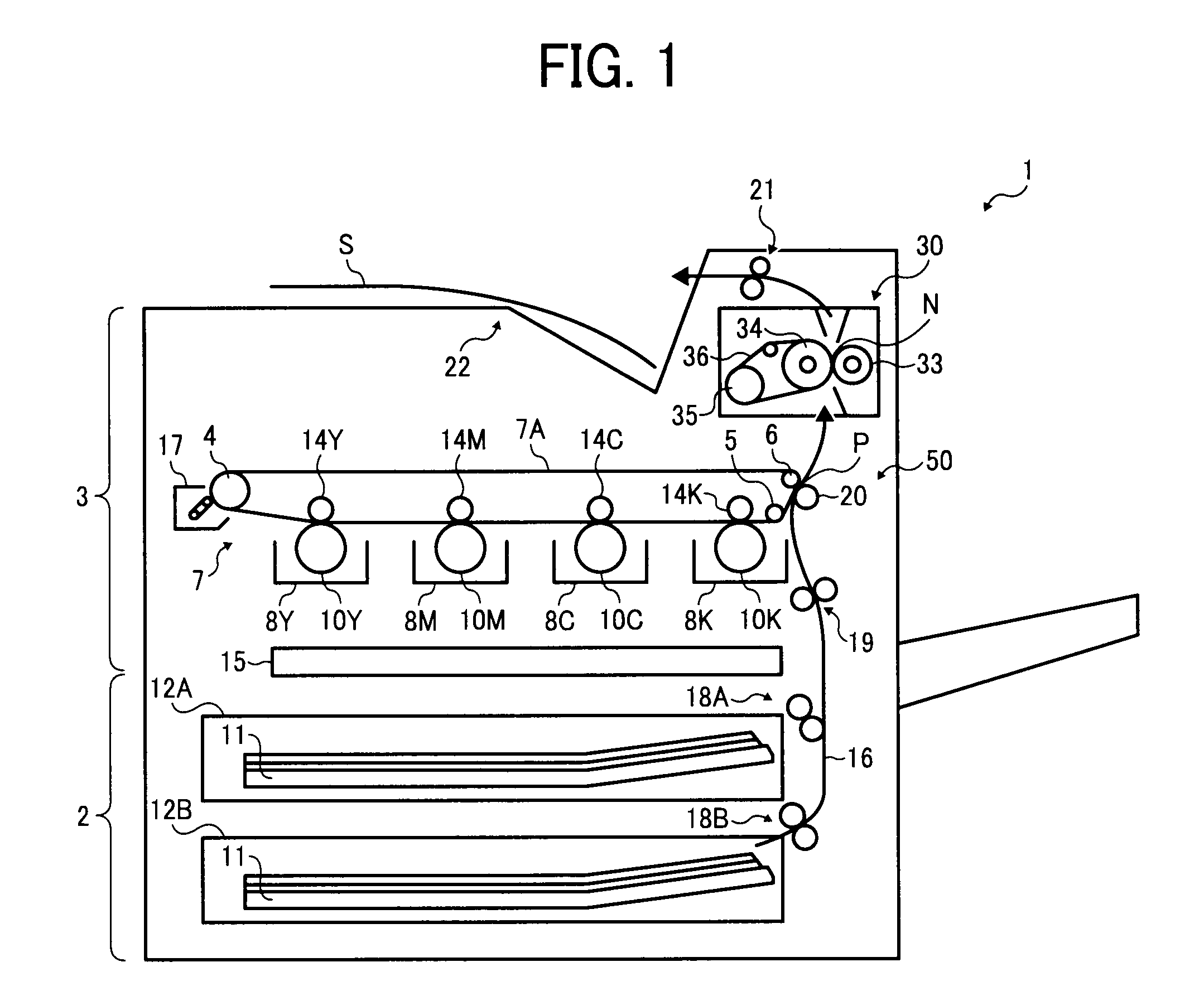
[0021]FIG. 1 schematically illustrates an embodiment of an image forming apparatus 1 according to this patent specification.

[0022]As shown in FIG. 1, the image forming apparatus 1 is configured as a color printer, with a lower sheet feeding section 2 and an upper printing section 3.

[0023]In the image forming apparatus 1, the sheet feeding section 2 includes stacked sheet trays 1...


PUM


Abstract

An image forming apparatus includes a transfer unit, a fuser unit, a relative positioning mechanism, and a fine adjustment mechanism. The transfer unit has a transfer nip to transfer an image from an imaging surface to a recording sheet passing therethrough. The fuser unit has a fixing nip to fix the transferred image on the recording sheet passing therethrough. The relative positioning mechanism is configured to position the transfer unit and the fuser unit relative to each other by contacting a contact portion with a flange. The contact portion is formed on one of the transfer unit and the fuser unit. The flange is formed on the other of the transfer unit and the fuser unit. The fine adjustment mechanism is configured to align the transfer nip and the fusing nip relative to each other.

Description

CROSS-REFERENCE TO RELATED APPLICATIONS[0001]The present patent application claims priority pursuant to 35 U.S.C. §119 from Japanese Patent Application No. 2007-294285 filed on Nov. 13, 2007, the contents of which are hereby incorporated by reference herein in their entirety.BACKGROUND OF THE INVENTION[0002]1. Field of the Invention[0003]The present invention relates to an image forming apparatus, such as a photocopier, facsimile, printer, plotter, or multifunctional machine with image forming capabilities, and more particularly, to an electrophotographic image forming apparatus having a transfer unit and a fixing unit, where an image formed on a photoconductor or intermediate transfer member is transferred and fixed onto a recording sheet while successively passing through a transfer nip and a fixing nip arranged in conjunction with each other.[0004]2. Discussion of the Background[0005]In electrophotographic image formation, an electrostatic latent image is formed through charging ...

Claims


Application Information

Patent Timeline
IPC IPC(8): G03G15/20
CPCG03G15/161G03G15/2064G03G15/1605G03G2221/1639G03G2221/1642G03G15/657
Inventor EHARA, MASANAOYAMAGUCHI, YOSHIKIIWAYA, NAOKI
Owner RICOH KK
Why Eureka
Try Eureka