Optical Disk Apparatus

a technology of optical disks and drives, applied in the direction of data recording, information storage, instruments, etc., to achieve the effect of reducing manufacturing costs and simplifying the driving mechanism of the disk transportation

Inactive Publication Date: 2009-05-14
MITSUBISHI ELECTRIC CORP
View PDF3 Cites 7 Cited by
  • Summary
  • Abstract
  • Description
  • Claims
  • Application Information

AI Technical Summary

Benefits of technology

[0013]According to the optical disk apparatus of the present invention, the disk transport mechanism includes the transport roller and rotation plane converting gear converting the rotation driving force of the shared motor transmitted via the first gear group into the rotation driving force for the transport roller. Therefore, the driving mechanism for disk transportation is simplified, which can achieve size reduction of the drive as well as reduction in manufacturing costs.

Problems solved by technology

The above-described conventional optical disk apparatus is configured to mount an optical disk on the disk tray, and is not adapted to what is called a slot-in type of directly loading / unloading an optical disk.

Method used


Image

  • Optical Disk Apparatus
  • Optical Disk Apparatus
  • Optical Disk Apparatus

Examples


embodiment

[0026]

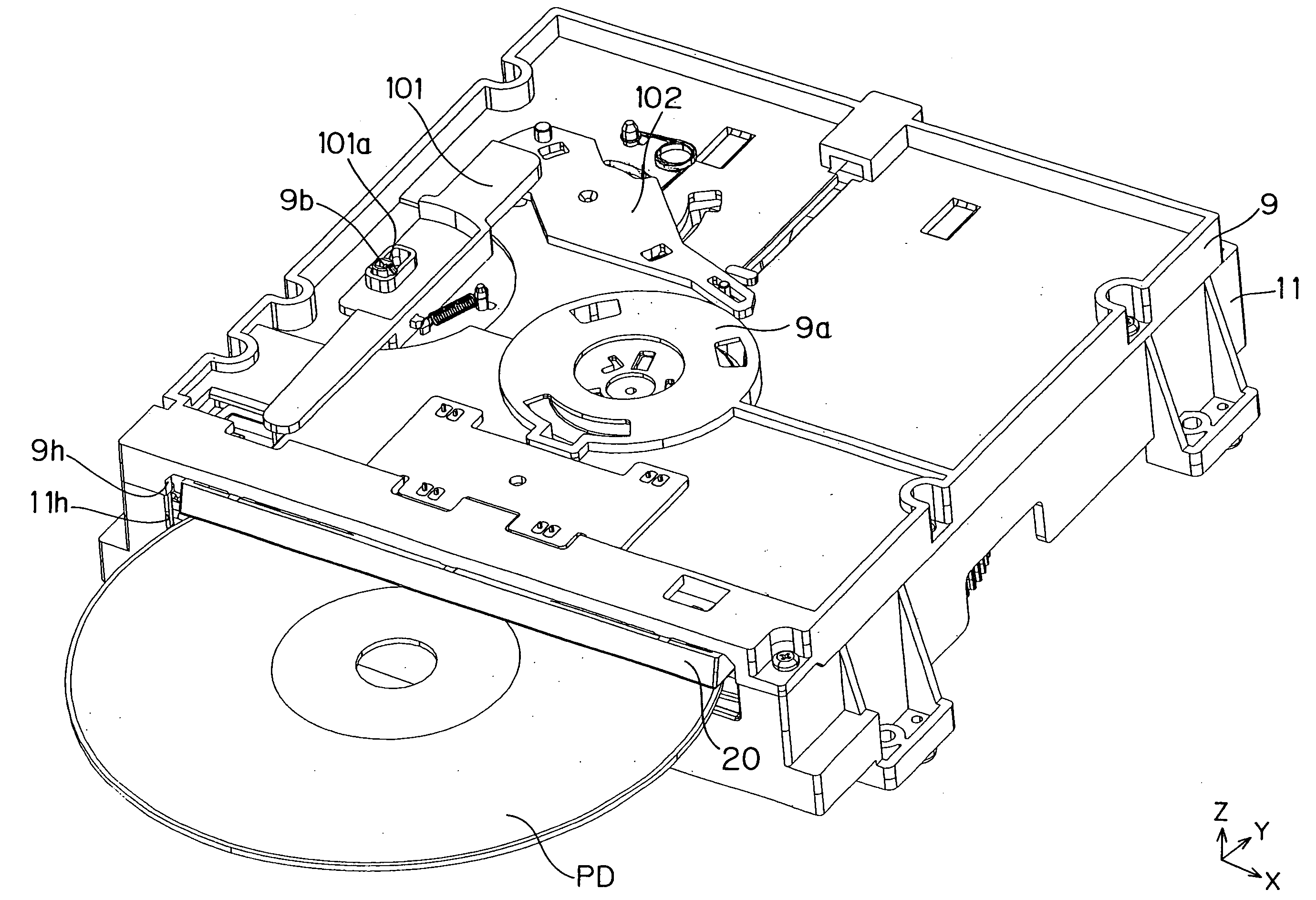
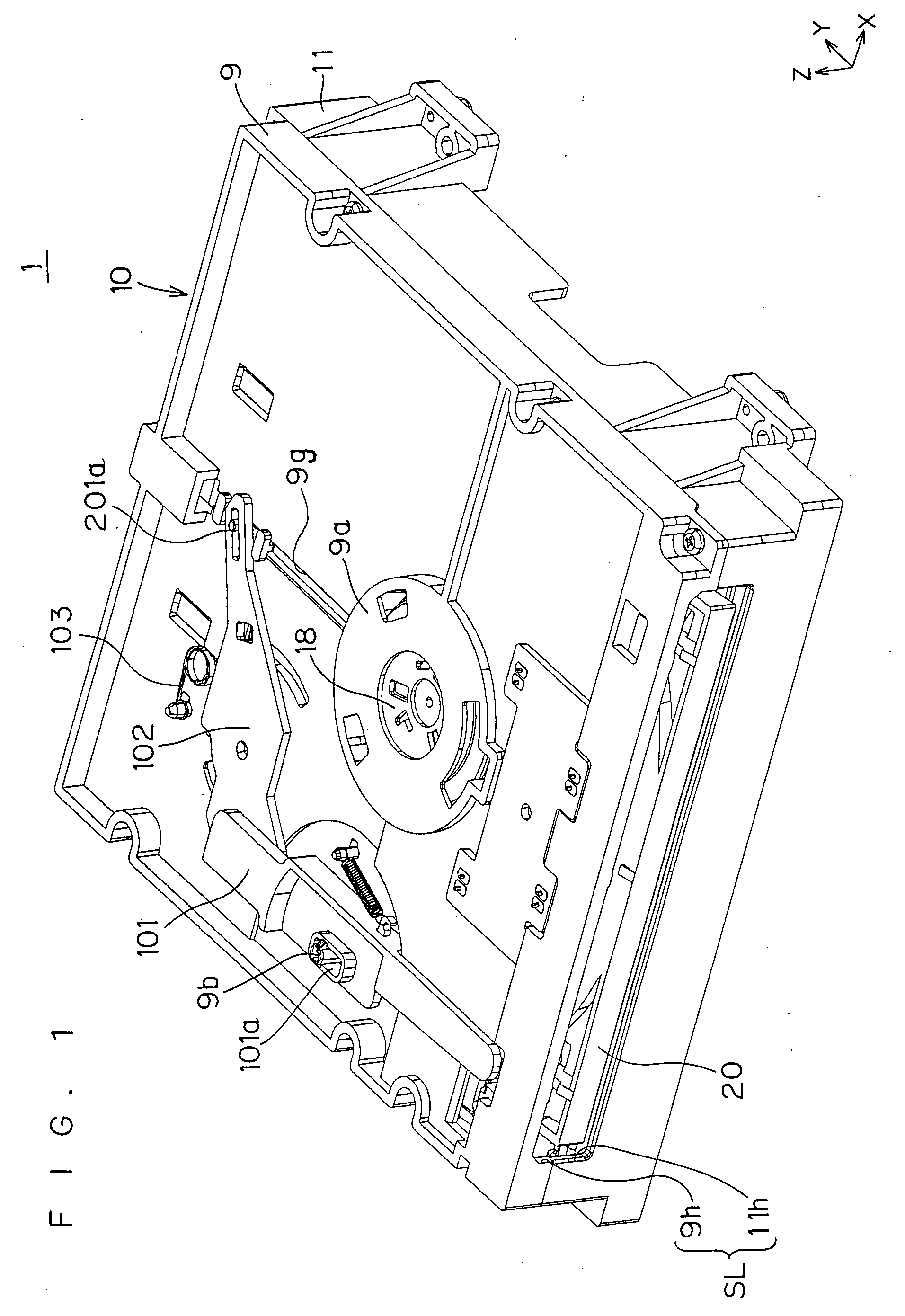
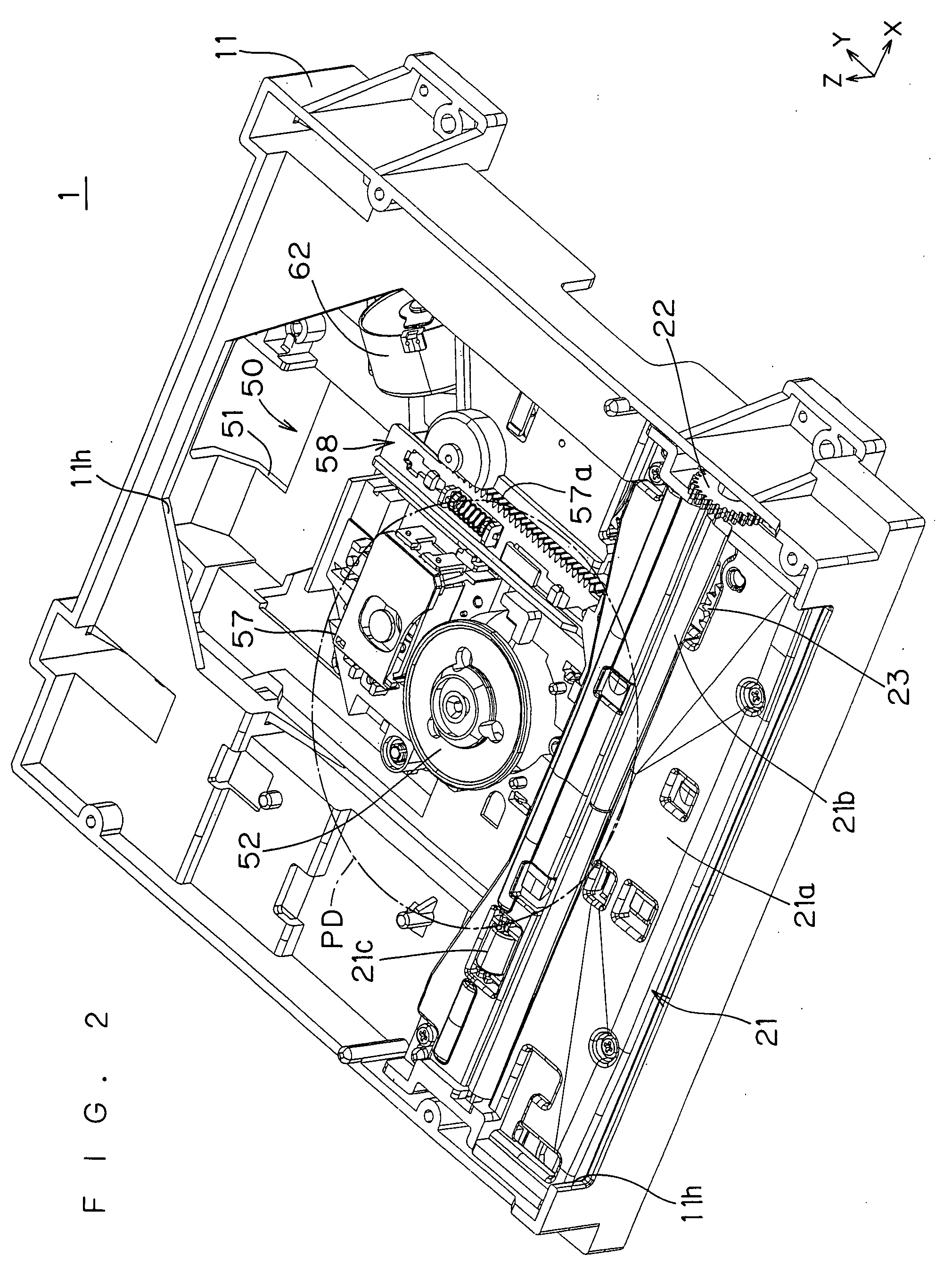
[0027]The basic construction of an optical disk apparatus 1 according to an embodiment of the present invention will be described using FIGS. 1 and 2.

[0028]FIG. 1 is a perspective view showing an external construction of the optical disk apparatus 1 when viewed slantingly from above. The following description will be made, for the sake of description, defining an axis parallel to the loading / unloading direction of an optical disk as a Y axis (the optical disk loading direction will be referred to as a (+)Y direction, and the optical disk unloading direction will be referred to as a (−)Y direction), an axis perpendicular to the Y axis on the main surface of the optical disk as an X axis (the right side in the (+) direction of the Y axis will be referred to as a (+)X direction, and the left side will be referred to as a (−)X direction), and an axis perpendicular to the main surface of the optical disk as an Z axis (the labeled surface side of the optical disk will be referred to...


PUM


Abstract

A traverse chassis supported in a swingable manner with respect to the main chassis and a disk transport plate provided along an opening are provided in the main chassis. The transport plate has a base part having a slender rectangular shape in plan view and a transport roller provided in the surface of the base part so as to extend in the longitudinal direction of the base part. The transport roller is provided such that its rotationally-moving shaft extends in parallel to an X direction, and an optical disk mounted on these components is loaded into or unloaded from an optical disk apparatus by rotation of the transport roller.

Description

TECHNICAL FIELD [0001]The present invention relates to an optical disk apparatus for recording a signal on an optical disk serving as information recording medium, such as a compact disk (what is called a CD), a digital versatile disk (what is called a DVD) and the like, or reproducing a recorded signal.BACKGROUND ART [0002]There is a conventional optical disk apparatus provided with an opening in a front panel of the drive for allowing a disk tray to go in / out through the opening. In this optical disk apparatus, an optical disk is mounted on the disk tray come out through the opening, and thereafter, the optical disk is drawn into a predetermined position inside the drive together with the disk tray.[0003]This type of optical disk apparatus is configured such that, after an optical disk is drawn into and held in the inside of the drive, a turn table rises from a predetermined lowered position to a predetermined raised position so that the optical disk is mounted on the turn table, ...

Claims


Application Information

Patent Timeline
Patent Type & Authority Applications(United States)
IPC IPC(8): G11B17/04
CPCG11B17/028G11B17/051G11B17/0404
Inventor FUKASAWA, AKIHIROMORI, KAZUO
Owner MITSUBISHI ELECTRIC CORP
Why Eureka
Try Eureka