Screw fastening machine

Inactive Publication Date: 2009-05-21
MAKITA CORP
View PDF2 Cites 9 Cited by
  • Summary
  • Abstract
  • Description
  • Claims
  • Application Information

AI Technical Summary

Benefits of technology

[0010]According to this invention, the holding part for holding the screw fastening depth regulating member removed from the working area or the tip end region of the machine body is provided in an area other than the tip end region of the machine body. Therefore, when the screw fastening operation is performed with the screw fastening depth regulating member removed from the machine body, for example, due to operation in a tight place, the removed screw fastening depth regulating member can be held in an area other than the tip end region of the machine body. Thus, loss of the screw fastening depth regulating member can be prevented. Further, the holding part is designed such that the screw fastening depth regulating member can be attached to and removed from the holding part by utilizing elastic deformation of the holding part. Therefore, the storage region for the screw fastening depth regulating member can be rationally formed by a smaller number of parts.
[0011]Further, ac

Problems solved by technology

The screw fastening depth regulating member provided in the tip end region of the machine body may interfere with a screw fastening operation, for exampl

Method used


Image

  • Screw fastening machine
  • Screw fastening machine
  • Screw fastening machine

Examples


Embodiment Construction

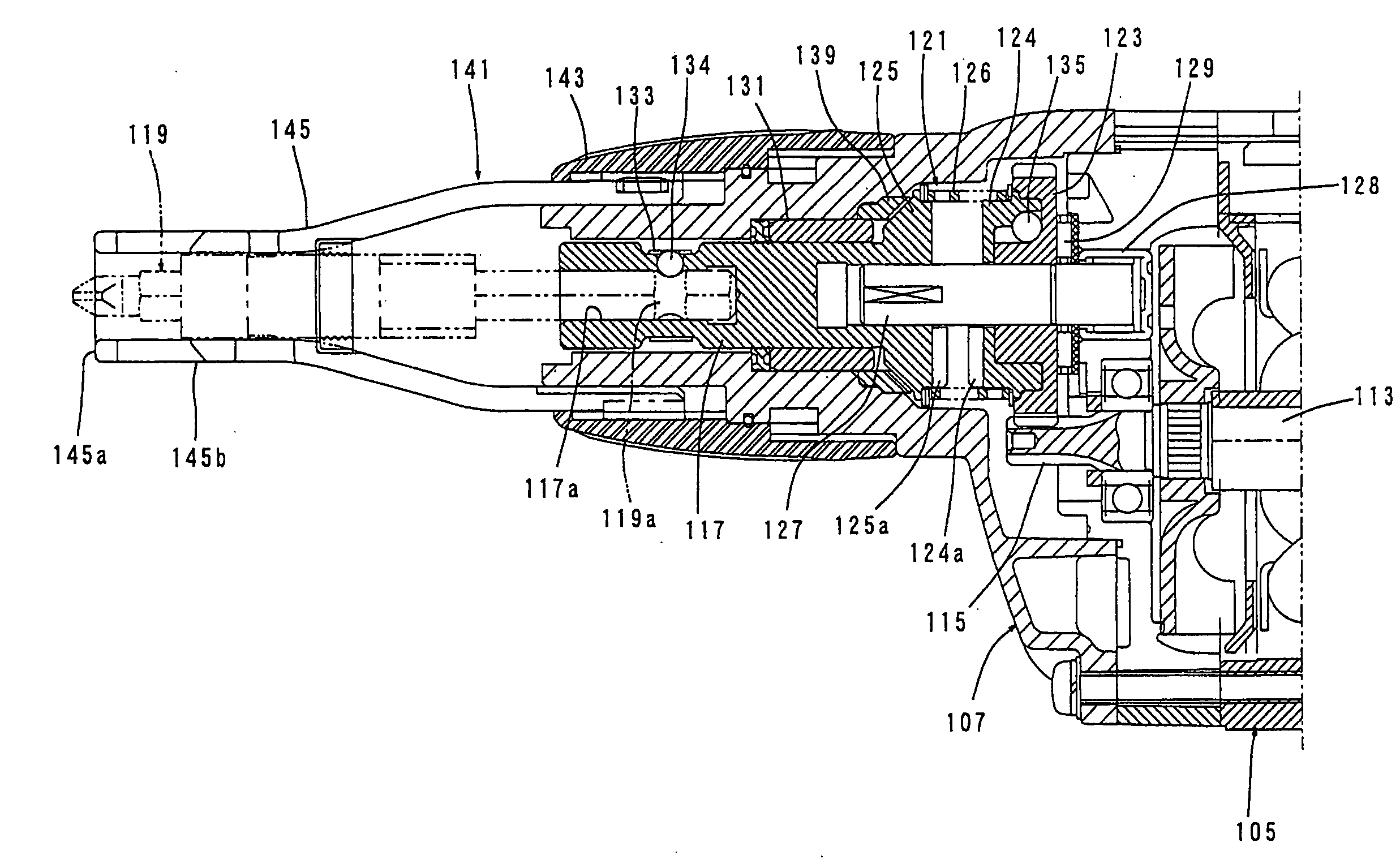
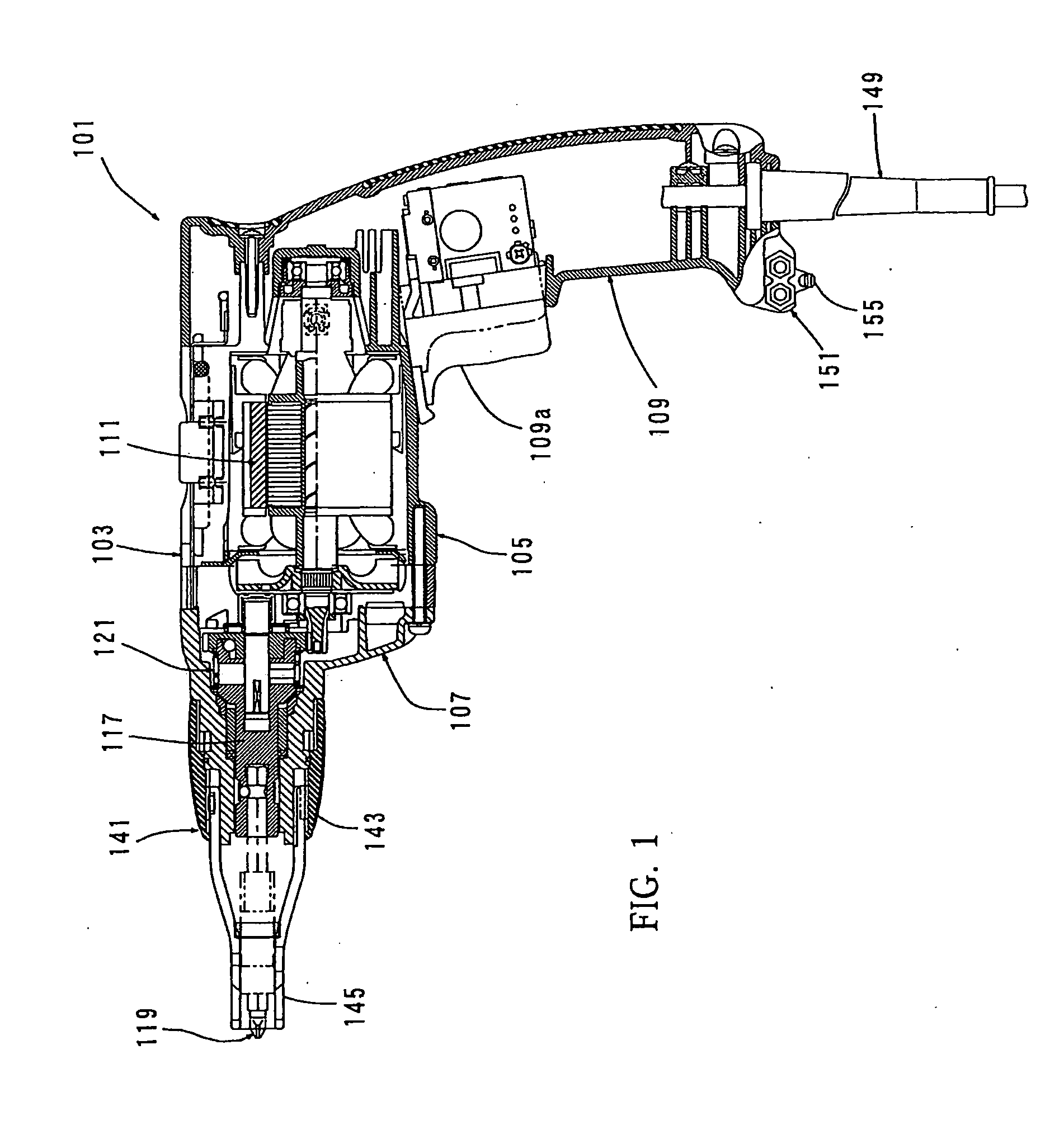
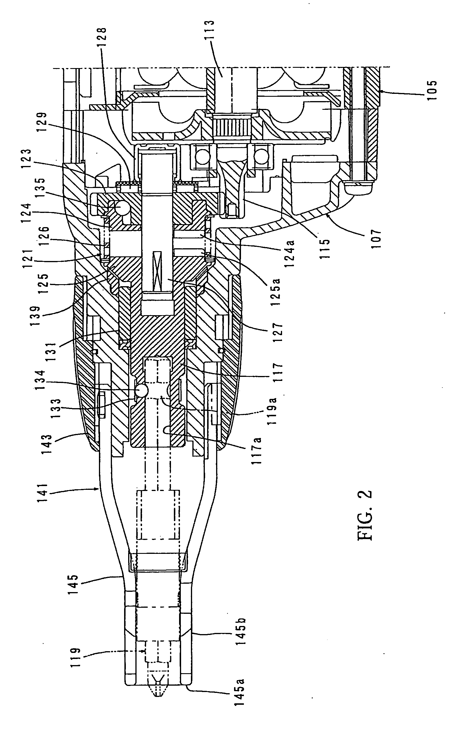
[0024]A representative embodiment of the present invention is now described with reference to FIGS. 1 to 5. FIG. 1 shows an entire electric screwdriver 100 as a representative embodiment of the screw fastening machine according to the present invention. The screwdriver 100 of this embodiment includes a body 103, and a driver bit 119 detachably coupled to the tip end region (on the left side as viewed in FIG. 1) of the body 103 via a spindle 117. The body 103, the spindle 117 and the driver bit 119 are features that correspond to the “machine body”, the “output shaft” and the “tool bit”, respectively, according to the present invention.

[0025]The body 103 includes a motor housing 105 that houses a driving motor 111, and a gear housing 107 that houses an engagement clutch 121, and a handgrip 109 designed to be held by a user and connected to the motor housing 105 on the side opposite to the driver bit 119. The engagement clutch 121 transmits the rotating output of the driving motor 111...


PUM


Abstract

It is an object of the invention to provide an effective technique for preventing loss of a screw fastening depth regulating member removed from a machine body in a screw fastening machine. A representative screw fastening machine includes a machine body, a motor, an input shaft, an output shaft, a first clutch element, a second clutch element, a biasing member for first and second clutch elements, a screw fastening depth regulating member. The machine body has a holding part formed in an area other than the tip end region of the machine body to removably hold the screw fastening depth regulating member. The holding part is provided such that the screw fastening depth regulating member can be attached to and removed from the holding part by utilizing elastic deformation of the holding part.

Description

BACKGROUND OF THE INVENTION[0001]1. Field of the Invention[0002]The present invention relates to a screw fastening machine that performs a screw fastening operation by a tool bit which is rotationally driven by a motor, and more particularly to a screw fastening machine that has a function of regulating a screw fastening depth.[0003]2. Description of the Related Art[0004]As a representative example of a screw fastening machine, Japanese laid-open patent publication No. 2000-246657 discloses an electric screwdriver designed and configured such that a screw fastening operation is completed when a screw is driven to a predetermined depth. In the known screwdriver, a screw fastening depth regulating member for regulating the screw fastening depth is provided in the tip end region of a machine body. When a screw is driven into a workpiece to a predetermined depth in a screw fastening operation, the screw fastening depth regulating member contacts the surface of the workpiece. Therefore, ...

Claims


Application Information

Patent Timeline
IPC IPC(8): B23Q5/00
CPCB25B21/00B25B23/141B25B23/0064
Inventor MIYAZAWA, MASAMICHIMATSUURA, YUTA
Owner MAKITA CORP
Why Eureka
Try Eureka