Supercharge Your Innovation With Domain-Expert AI Agents!

Pneumatic angular gripper

Inactive Publication Date: 2009-05-21
GIMATIC SRL
View PDF3 Cites 4 Cited by
  • Summary
  • Abstract
  • Description
  • Claims
  • Application Information

AI Technical Summary

Benefits of technology

[0007]One object of the present invention is to provide a pneumatic angular gripper that avoids the drawbacks and disadvantages of the known technique, more simple and economic to manufacture and where the jaws are positioned and pulled externally on the two opposite sides of the body of the gripper and the fulcrums or oscillating arbours of said jaws are housed in the body and connected to the stem of the control piston in an innovative way.
[0009]A further object of the invention is to provide a pneumatic angular gripper which can be fitted out in only one size, but with the possibility of increasing the gripping power as much as to double it without basically increasing its dimensions.

Problems solved by technology

However, this realisation has some faults regarding the assembly and precision in controlling the rotation movements of the jaws when they move from the open to the closed position.
This arrangement, however, means that in the body of the gripper both a housing for the jaws and the crossways housing for the pin or oscillating fulcrum of the joys must be provided, with the result that at least the execution and assembly of the gripper become laborious and costly to carry out.

Method used


Image

  • Pneumatic angular gripper
  • Pneumatic angular gripper
  • Pneumatic angular gripper

Examples


Embodiment Construction

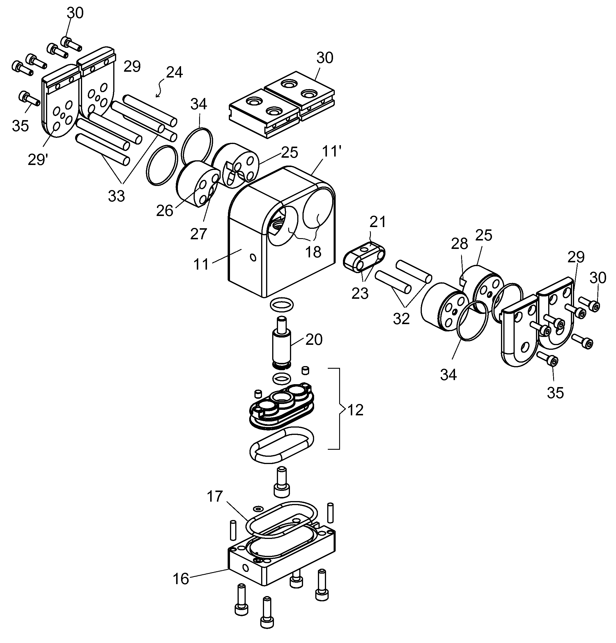
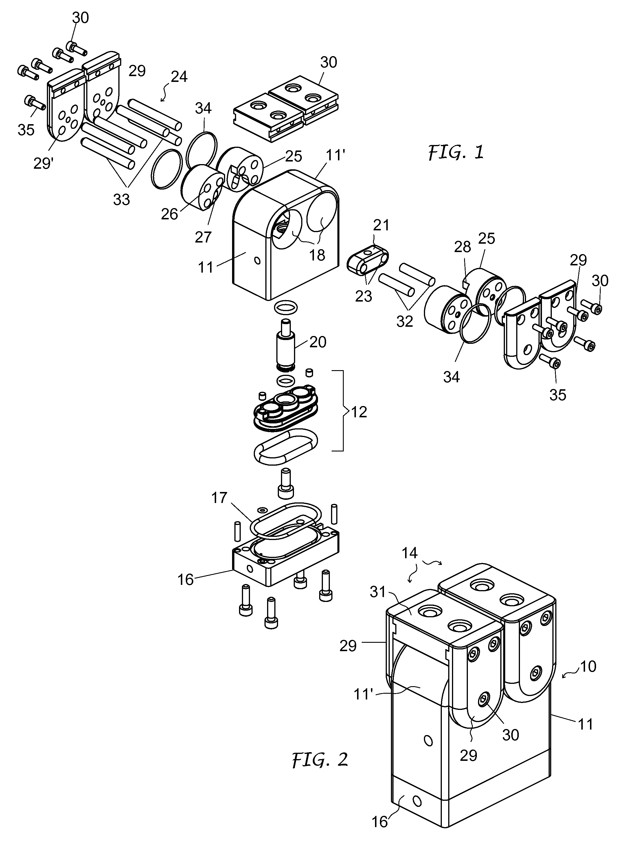
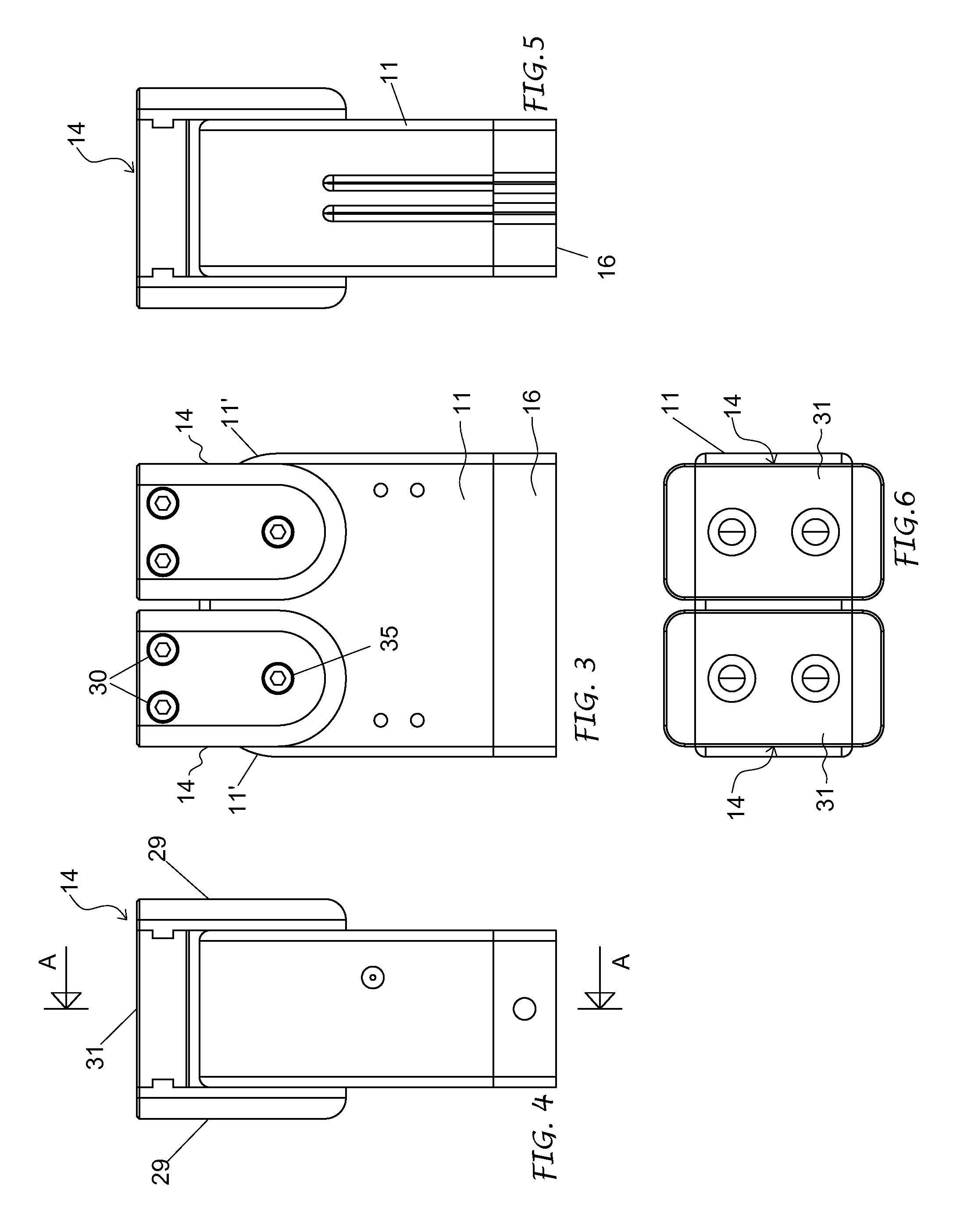
[0019]In said drawings, the pneumatic angular gripper is designed globally by the number 10 and basically includes a prismatic gripper body 11, a pneumatic control piston 12, two fulcrums or oscillating arbours 13 and two gripper jaws 14.

[0020]The gripper body 11 can be a single piece made by sintering. Internally it forms a chamber 15 closed by a bottom plate 16 with the interposition of a seal 17 and has, at its top, two cylindrical transversal housings 18 which are in communication with said chamber by means of an intermediate bore 19. The two cylindrical housings 18 are parallel between them, in symmetrical positions compared to the intermediate bore 19 and lying in an orthogonal plane with regard to the axis of said bore. The top of the gripper body 11 has rounded opposite parts 11′ which centres of curvature are on the axis of said cylindrical housings.

[0021]The control piston 12 is housed in said chamber 15 and susceptible to alternating movements due to the action of a fluid...


PUM


Abstract

This invention concerns a pneumatic angular gripper with gripper jaws (14), basically with an upside-down U shape, positioned astride the top of the gripper body and connected to respective fulcrums or oscillating arbours (13). The latter, turning and with self-supporting shape, are assembled in through cylindrical housings (18), parallel, provided transversely to the gripper body in an orthogonal plane to the stem of said control piston. The fulcrums or oscillating arbours are connected directly to the head connector (21) by means of sliding means (27, 33) and each to the respective gripper jaw (14) by anchoring means and rigid pulling spindles.

Description

FIELD OF THE INVENTION[0001]This invention concerns in general the pneumatic gripper sector used for gripping items being machined and / or for automatic handling, and refers in particular to a pneumatic angular gripper, more especially the control means of the jaws in said type of gripper.STATE OF THE TECHNIQUE[0002]Auto centring devices in the form of pneumatic grippers are already well-known and used in the field of machining and / or handling and / or automatic assembly of objects or items. Such grippers basically comprise a gripper body forming a chamber, a piston positioned and moving alternately in said chamber under the action of a fluid under pressure and a pair of gripper jaws pivoted to said body and movable in opposite directions on respective rotation axes. In the so-called angular grippers, the control piston is connected to the gripper jaws by a drawing means so that the linear movements of the piston correspond to the opening and closing angular movements of the jaws.[0003...

Claims


Application Information

Patent Timeline
IPC IPC(8): B66C1/00
CPCB25J15/0226
Inventor MAFFEIS, GIUSEPPEBELLANDI, GIUSEPPE
Owner GIMATIC SRL
Features
  • R&D
  • Intellectual Property
  • Life Sciences
  • Materials
  • Tech Scout
  • Unparalleled Data Quality
  • Higher Quality Content
  • 60% Fewer Hallucinations
Learn More