Connecting rod of a crank mechanism

Inactive Publication Date: 2005-02-15
SCHAEFFLER TECH AG & CO KG
View PDF11 Cites 7 Cited by
  • Summary
  • Abstract
  • Description
  • Claims
  • Application Information

AI Technical Summary

Benefits of technology

Due to its simple and inexpensive manufacture and its light weight coupled with high stiffness, the conne

Problems solved by technology

Due to these intended bending regions, these prior art connecting rods are not suitable for applicati

Method used


Image

  • Connecting rod of a crank mechanism
  • Connecting rod of a crank mechanism

Examples


Example

DETAILED DESCRIPTION OF THE DRAWINGS

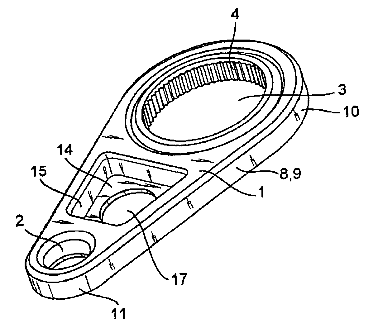
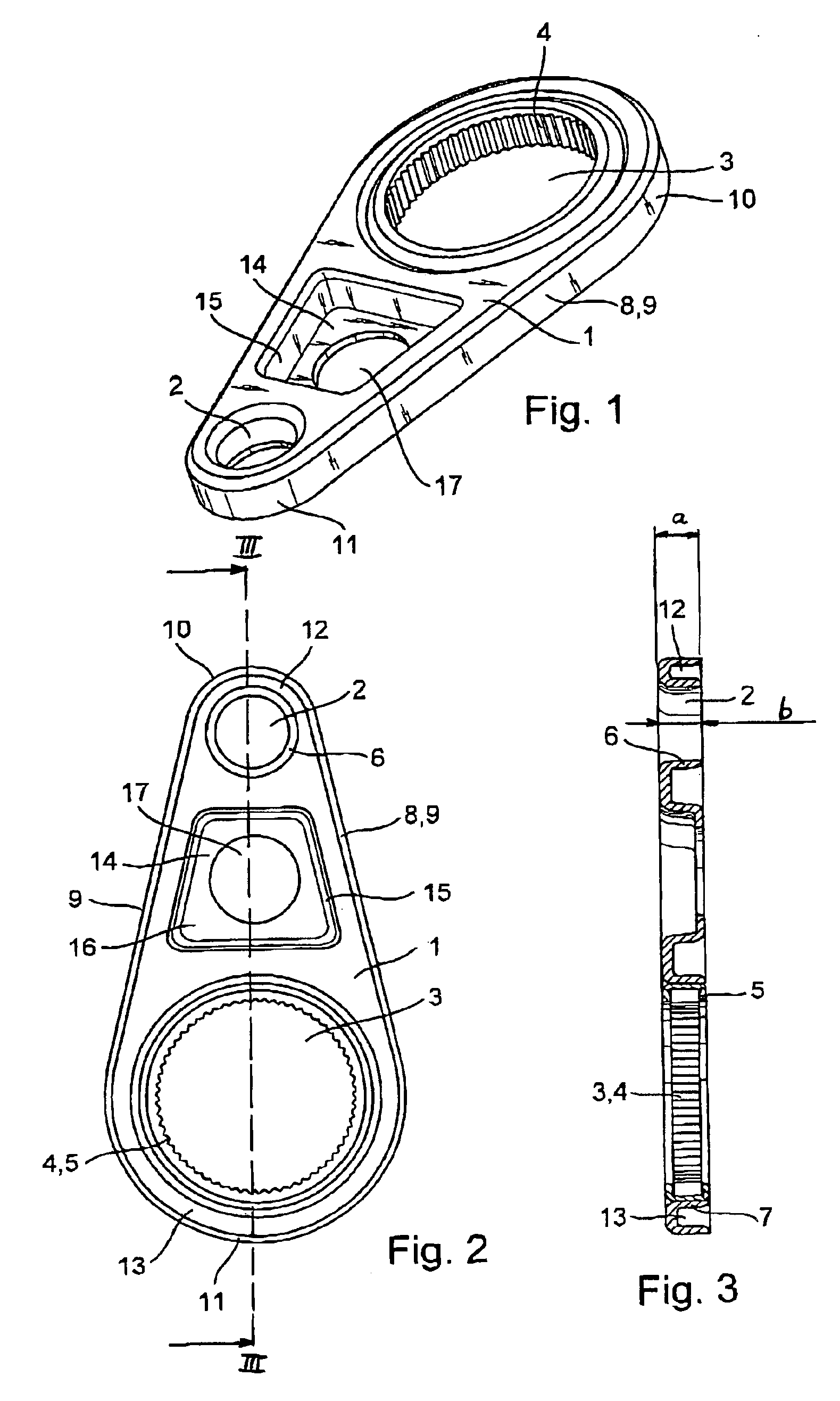
The connecting rod of the invention illustrated in FIGS. 1 to 3 is made out of sheet metal by deep drawing out of a single piece of sheet metal. The connecting rod comprises a base sheet 1 comprising an upper connecting rod eye 2 and a lower connecting rod eye 3. The lower connecting rod eye 3 comprises a rolling element crown ring 4 for enabling a perfect mounting of this connecting rod on a crank, not shown. An outer ring 5 of the rolling element crown ring 4 is pressed into the lower connecting rod eye 3.

Each of the connecting rod eyes, 2 and 3, comprises a cylindrical stamping 6, 7 that is formed integrally on the base sheet 1. These stampings 6, 7 form cylindrical mountings that, as described above, can receive, for instance, a rolling element crown ring.

Starting from the bottom plane of the base sheet 1, a stiffening collar 8 is formed integrally on the peripheral edge of the sheet metal part. The stiffening collar 8 has a continuous, uninte...


PUM

PropertyMeasurementUnit
Dimensionaaaaaaaaaa

Abstract

A connecting rod of a crank mechanism is made as a single sheet metal part by shaping without chip removal out of sheet metal. The connecting rod comprises a base sheet (1) that is provided with an upper connecting rod eye (2) and a lower connecting rod eye (3). Each of the connecting rod_eyes (2, 3) has an integral cylindrical stamping (6, 7). The connecting rod further comprises a stiffening collar (8) that is integrally formed out of the base sheet (1) and is configured without interruption on the periphery of the base sheet (1).

Description

FIELD OF THE INVENTIONThe present invention concerns a connecting rod of a crank mechanism. Connecting rods are usually mounted with their lower connecting rod eye for rotating on a crank and are pivotally connected through their upper connecting rod eye, for example, to a piston.BACKGROUND OF THE INVENTIONDE 38 01 802 C2, for example, discloses a connecting rod for an axial piston compressor. The connecting rod is made of shaped sheet metal whose base sheet comprises deep drawn cylindrical stampings for the connecting rod eyes on both ends. A bearing bushing is inserted into each connecting rod eye and the cylindrical stamping overlaps only a part of the axial length of the bushing. Reinforcing beads are also provided to impart increased stiffness to the connecting rod in defined sections. However, along a straight line extending transversely of a central longitudinal axis of the connecting rod, the base sheet is not shaped. Bending can occur more easily along the straight line ext...

Claims


Application Information

Patent Timeline
IPC IPC(8): F16C7/00F16C7/02F16C7/08
CPCF16C7/023F16C7/08Y10T74/2142Y10T29/49288Y10T74/2162
Inventor JAGER, STEFANRADINGER, NORBERTFICK, MATTHIAS
Owner SCHAEFFLER TECH AG & CO KG
Why Eureka
Try Eureka