[0002]The connecting element according to the present invention and the method according to the present invention for manufacturing a connecting element have the
advantage over the related art that during the injection molding operation for manufacturing the housing, the line part is reinforced and stiffened with the aid of the stiffening element in such a way that bending or torsion of the line part due to the injection molding operation is mostly suppressed. Mechanical stresses in the material of the line part are thus advantageously prevented, thereby increasing the lifetime of the connecting element on the one hand, and increasing the tightness of the connecting element, in particular at the transitions between the line part and the housing, on the other hand. In addition,
assembly tolerances are minimized, so that the position and alignment of the electrical component are not impaired. When using a sensor as an electrical component in particular, an increase in the measuring accuracy obtainable with the sensor is thus achieved. The line part preferably includes a metallic insert, which is at least partially enclosed by the housing. The electrical component preferably includes a mechanical, a micromechanical, an electrical, an electronic and / or a
Hall effect sensor element. It is optionally conceivable that the electrical component includes an additional internal housing. For example, the electrical component has an SOIC or LGA design or the like. Alternatively, the stiffening element is connected to the line part either permanently or only temporarily (essentially only for the duration of the injection molding operation). The connecting element preferably has a plurality of stiffening elements.
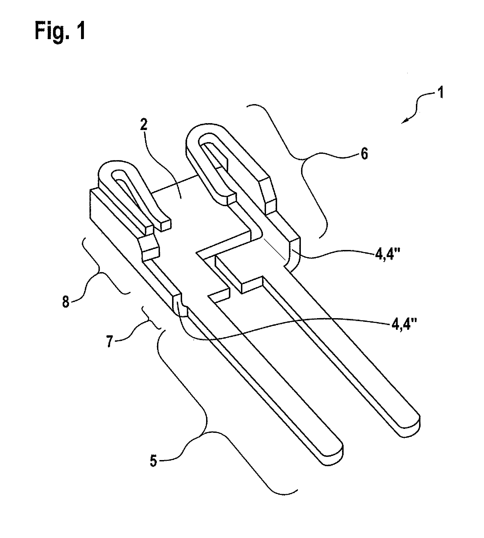
[0003]According to one preferred specific embodiment of the present invention, it is provided that the stiffening part includes a bent area of the line part. The stiffening part is preferably designed in one piece with the line part. Thus a comparatively simple and inexpensive manufacture of the stiffening part is advantageously possible, in which one area of the line part is simply bent over, for example. This creates a bending edge or a fold in particular, so that a substantial reinforcement of the line part is achieved. The line part therefore has an L-shaped cross section in the area of the bent area in particular.
[0005]According to one preferred specific embodiment of the present invention, it is provided that the stiffening part includes a separate plastic part, preferably being situated in a holding area between the plug area and the sheathing area and / or being connected to the line part in a form-locked manner. The line part is advantageously reinforced with the aid of the separate stiffening part manufactured from plastic. The stiffening part is preferably simply attached to the line part and in particular is not manufactured by
extrusion-
coating of the line part, so that unintentional bending of the line part by the stiffening part need not be feared. The stiffening part includes, for example, a premolded plastic part. Due to a form lock between the plastic part and the line part, unintentional bending or torsion of the line part during the
injection molding process for manufacturing the housing is prevented. It is conceivable that the plastic part is also sheathed during the injection molding operation. It is optionally conceivable that the line part is reinforced by a stiffening element designed in the form of the bent area as well as by the stiffening element manufactured separately of plastic.
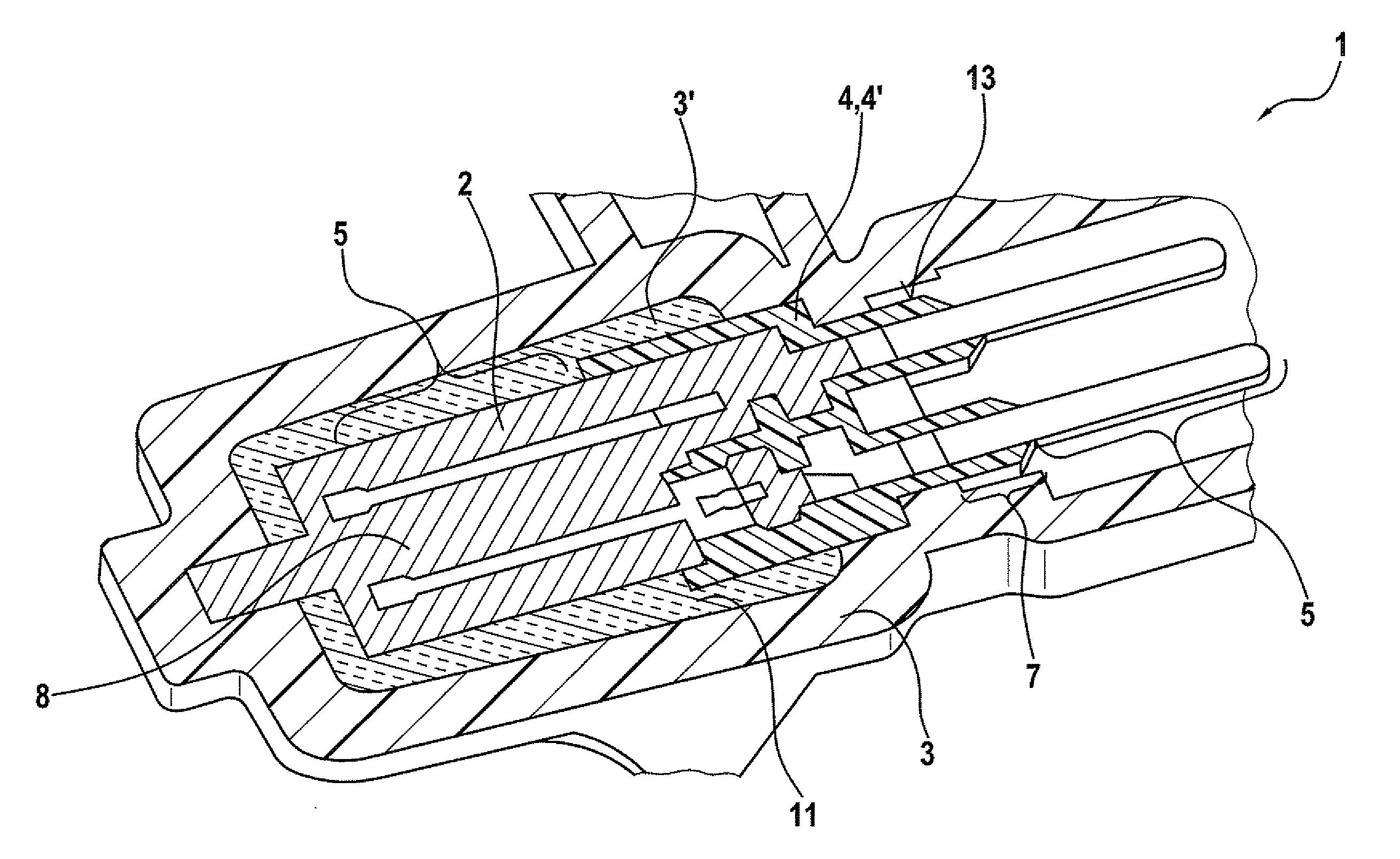
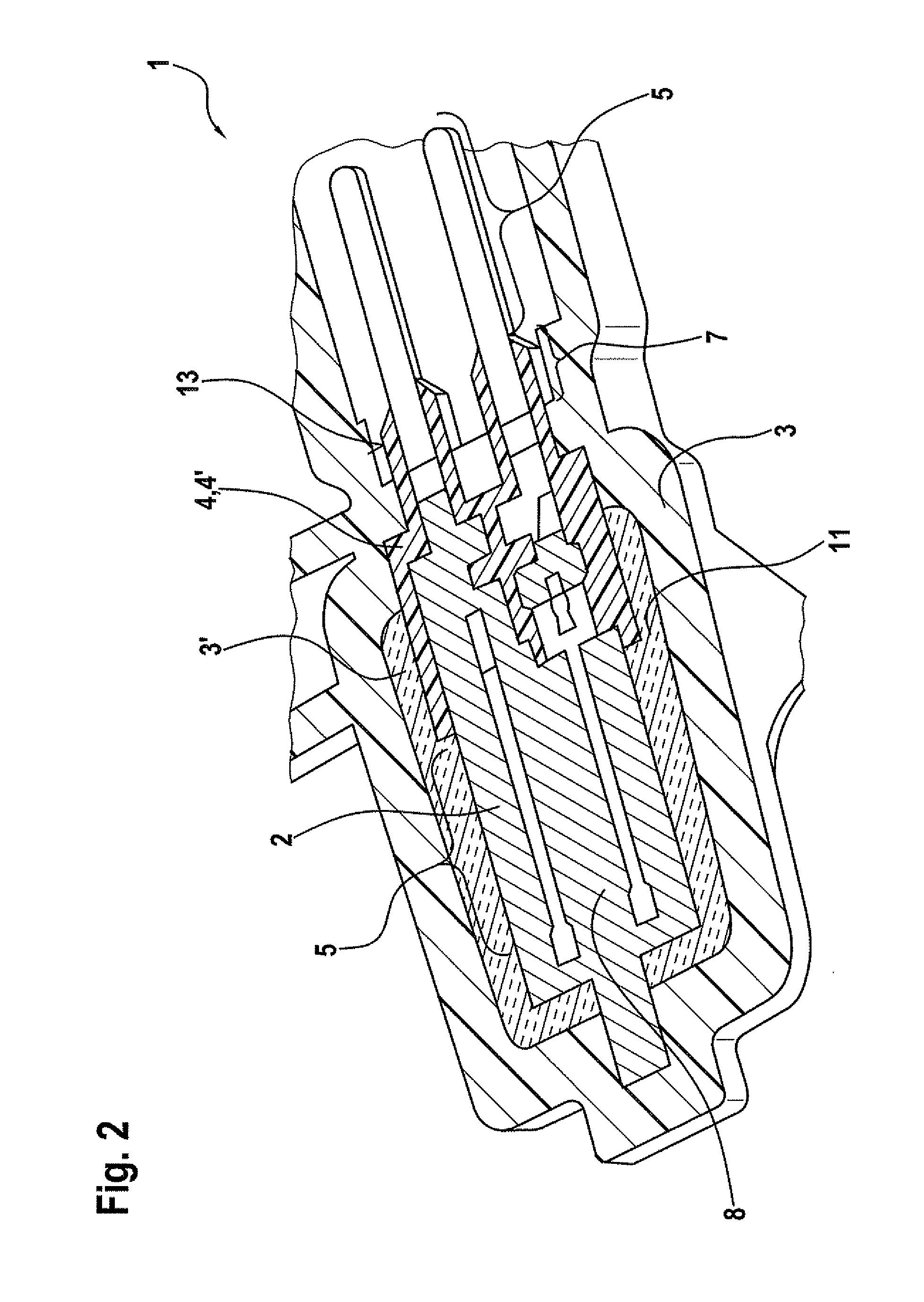
[0006]According to one preferred specific embodiment of the present invention, it is provided that the line part has a receiving area for receiving the electrical component, in particular a sensor element, the receiving area being preferably situated between two stiffening elements and in particular between two bent areas. The receiving area is used to fasten the electrical component. The receiving area and the electrical component are preferably sheathed during the injection molding operation for manufacturing the housing, so that the housing protects the electrical component from external environmental influences such as
mechanical force effects,
moisture, soiling and the like. The optional configuration of the receiving area between at least two stiffening elements and in particular between two bent areas has the
advantage that bending or torsion of the line part is effectively prevented precisely in the sensitive area of the electrical component.
[0008]According to one preferred specific embodiment of the present invention, it is provided that the line part in the second method step is bent at least partially to form a bent area which functions as a stiffening element. A comparatively simple and inexpensive manufacture of the stiffening element is thus advantageously achieved because the line part need only be bent. A substantial reinforcement of the line part is achieved due to the resulting fold.
[0010]According to one preferred specific embodiment of the present invention, it is provided that the line part is secured in the area of the stiffening element during the third method step. This achieves a mechanically
stable fixation of the line part during the injection molding operation, in which the risk of bending or torsion of the line part is minimized. Using the separate plastic part also has the
advantage that additional holding and gripping surfaces are created for fixation of the connecting element during the injection molding operation. A clamping hold of the connecting element on the separate plastic part during the injection molding operation is possible in particular without resulting in any metallic abrasion on the line part. It is conceivable that a full-area or partial-area support of the separate plastic part in the sheathing tool is achieved by a form lock. Due to the full utilization of the plug base, a maximum support of the line part in the sheathing tool is then achieved.

