Method for producing a cylindrical optical component of quartz glass and optically active component obtained by said method

a technology of quartz glass and optical active components, which is applied in the direction of glass shaping apparatus, lasers, laser construction details, etc., can solve the problems of device itself and the adjustment of the components, undesired non-linear effects, and deformation of the core region,

Inactive Publication Date: 2013-08-13
HERAEUS QUARZGLAS
View PDF16 Cites 1 Cited by
  • Summary
  • Abstract
  • Description
  • Claims
  • Application Information

AI Technical Summary

Benefits of technology

[0021]It is the object of the present invention to provide a method which permits a simple and inexpensive manufacture of a cylindrical optical component made of quartz glass, which is provided with a radial layer exhibiting a varying wall thickness at least over part of its length.
[0022]Furthermore, the present invention is based on the object to provide a blank for an optically active component in which a minor impairment of the core zone in the area of the input point of the pump light and the occurrence of non-linear effects caused by high absorption of the pump light can largely be avoided, and wherein a high degree of efficiency of the pump light is attained.

Problems solved by technology

This is accompanied by a degradation of the core region due to heat action and photodarkening.
Moreover, the high energy density of the pump light in the input region on the one hand and the exponential decrease in the pump light power on the other hand lead to undesired non-linear effects.
The device itself and the adjustment of the components are however very complicated.
The manufacture of a laser component with a conically tapering pump light cladding of glass does however pose some problems.
This procedure is troublesome and requires a complicated control process, and it is particularly not suited for setting a steep cone angle (e.g. more than 10°).
For instance, cooling over a solid body turns out to be more difficult to realize than cooling at a constant outer diameter, and the customizing of the laser component, particularly a laser fiber, is difficult.
Grinding entails a lot of work and great loss of material.
The known methods require great efforts in terms of work and time for producing a cylindrical outer diameter of the optical component.
This means that he blank permits an elongation with a large draw ratio without the cone angle of the pump light zone becoming inefficiently flat for the out-coupling of pump light.
With a mean decrease in intensity of less than 1% / m there is a light guidance in the pump light zone over an output path with a length of more than 100 m for a complete out-coupling of the pump light, which—depending on the type of the optically active component and the pump light zone—can be accompanied by a noticeable loss due to optical attenuation of the pump light.
This reduces the absorption of the pump light in the region of the in-coupling area.
Using very long and low-doped active cores prevents a situation where the active core absorbs the pump light too much near the input point and the fiber is damaged by the evolving heat development or by an excessively high degree of inversion (photodarkening).
These long fibers, however, are limited by non-linear effects such as SRS and SBS (stimulated Raman and Brillouin scattering) in their usability.

Method used


Image

  • Method for producing a cylindrical optical component of quartz glass and optically active component obtained by said method
  • Method for producing a cylindrical optical component of quartz glass and optically active component obtained by said method
  • Method for producing a cylindrical optical component of quartz glass and optically active component obtained by said method

Examples


first embodiment

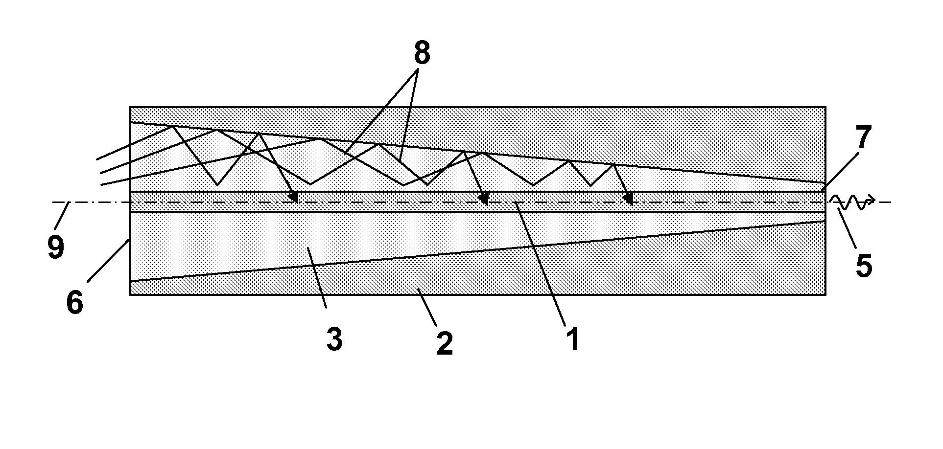
[0095]FIG. 9 shows an optically active component obtained from the blank in the form of a cylindrical laser fiber with a pump light zone that is ring-shaped in radial cross-section and conical in axial cross-section, in a longitudinal section;

second embodiment

[0096]FIG. 10 shows an optically active component in the form of a cylindrical laser fiber in a longitudinal section;

[0097]FIG. 11 shows a further variant of providing and joining preforms in the manufacture of an optically active component;

[0098]FIG. 12 shows a further variant of providing and joining preforms in the manufacture of an optically active component;

[0099]FIG. 13 shows a further variant of providing preforms in the manufacture of an optically active component;

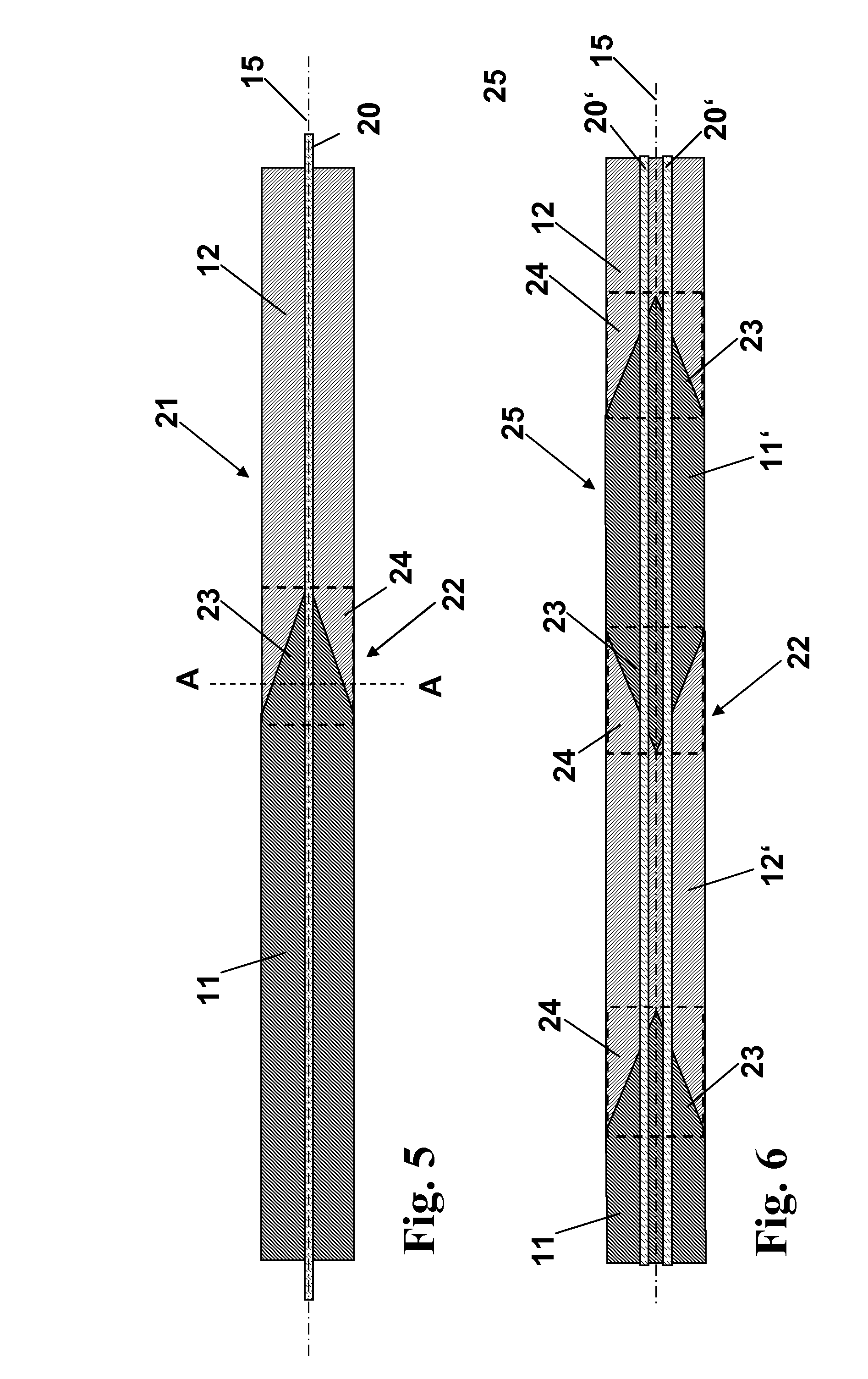
[0100]FIG. 14 shows the joining of the preforms of FIG. 13 on the face side with formation of a composite preform with an outer bead; and

[0101]FIG. 15 shows the quartz glass blank obtained after grinding off the outer bead of the composite preform of FIG. 14.

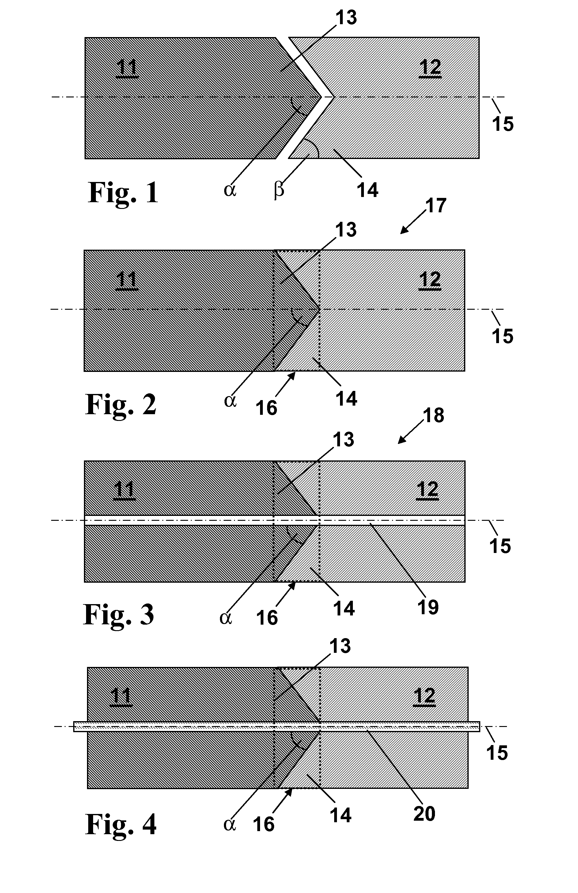
[0102]FIG. 1 schematically shows a first cylinder 11 of undoped quartz glass and a second cylinder 12 of a quartz glass doped with 4% by wt. of fluorine. The first cylinder has a face side ground in the form of a pointed cone 13. The second cylinder 12 has a fa...


PUM

PropertyMeasurementUnit
steep cone angleaaaaaaaaaa
mean cone angleaaaaaaaaaa
angleaaaaaaaaaa

Abstract

Cylindrical optical components of quartz glass are known, which have an inner zone made of an inner zone glass, which extends in the direction of the longitudinal axis and is surrounded by a jacket zone made of a jacket zone glass, the average wall thickness thereof varying at least over a part of its length in the direction of the longitudinal axis of the component. The aim of the invention is to provide a method that allows a simple and cost-effective production of such an optical component from quartz glass. A method is proposed according to the invention, comprising the following method steps: (a) providing a first parison made of an inner zone glass, which has a first contact surface on the end face, said contact surface having a conical external contour; (b) providing a second parison from the jacket zone glass; (c) embedding the contact surface with a conical external contour into the jacket zone glass and welding the contact surface to the jacket zone glass, thereby forming a composite parison which has a cone-shaped inner zone area of inner zone glass in a contact area, said inner zone area being surrounded by a jacket zone area having the shape of an inner cone; and (d) elongation of the composite parison to form the optical component or a preproduct of the component.

Description

[0001]The present invention relates to a method for producing a cylindrical optical component of quartz glass, comprising an inner zone extending in the direction of a longitudinal axis and made from an inner zone glass, which zone is clad by a cladding zone made from a cladding zone glass, the mean wall thickness of which is varying at least over part of the length thereof in the direction of the longitudinal axis of the component.[0002]Moreover, the present invention relates to a cylindrical blank for producing an optically active component, which comprises a longitudinal axis, at least one core extending along the longitudinal axis and consisting of an optically active material, a pump light layer extending along the core, and a cladding layer surrounding the pump light layer and having a lower refractive index than the pump light layer, the pump light layer having a decreasing wall thickness along an output path.TECHNICAL BACKGROUND[0003]Side pumped optically active components i...

Claims


Application Information

Patent Timeline
Patent Type & Authority Patents(United States)
IPC IPC(8): H01S3/30
CPCC03B23/207C03B37/01245H01S3/0602H01S3/063H01S3/06708C03B2201/12C03B2203/02C03B2203/18C03B2203/34H01S3/06745H01S3/094003H01S3/094007H01S3/1603H01S3/176
Inventor BAUER, PETERBRAEUER, KARSTENFLACH, MARCOLANGNER, ANDREASSCHMIDT, RICHARDSCHMITT, CLEMENSSCHOETZ, GERHARDSTECHER, MATTHIAS
Owner HERAEUS QUARZGLAS
Why Eureka
Try Eureka