Filter Element Having an End-Side Stand

a filter element and end-side stand technology, applied in the direction of filtration separation, lubricant mounting/connection, separation process, etc., can solve the problem of radial seal and/or sealing element damage, and achieve the effect of easy and economical production

Inactive Publication Date: 2020-06-11
MANN HUMMEL GMBH
View PDF0 Cites 2 Cited by
  • Summary
  • Abstract
  • Description
  • Claims
  • Application Information

AI Technical Summary

Benefits of technology

The invention provides an easily and economically producible filter element for a drainage channel of a filter head that is provided with a closure element protected from damage. The filter element comprises a stand that extends in axial direction away from the end face of the filter element to the level of the free end of the closure element or past the free end of the closure element. This stand allows for easy placement of the filter element on a support surface, in particular a conveyor belt, with the closure element facing in downward direction. The stand can be locked at the filter element, providing protection against mechanical damage to the closure element and other components of the filter element. The stand is designed to be robust and can be easily connected to the filter element. The stand can be connected to the filter element without changing its position, and it can be designed with a minimal material expenditure. The support ring can have a positioning pin that aligns with the drainage channel when mounting the filter element at the filter head. This makes it easy to engage the positioning pin with a stop element on the filter head.

Problems solved by technology

If it were attempted to place the filter insert onto its bottom side with the radial seal and the sealing element, there would therefore be the danger that the radial seal and / or the sealing element become damaged.

Method used


Image

  • Filter Element Having an End-Side Stand
  • Filter Element Having an End-Side Stand
  • Filter Element Having an End-Side Stand

Examples


Embodiment Construction

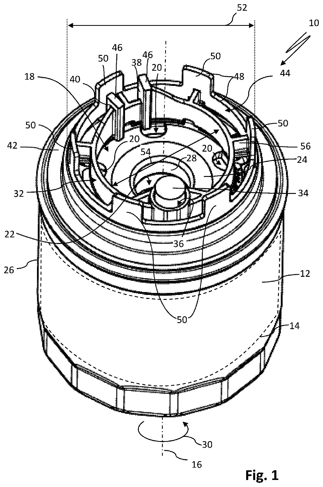
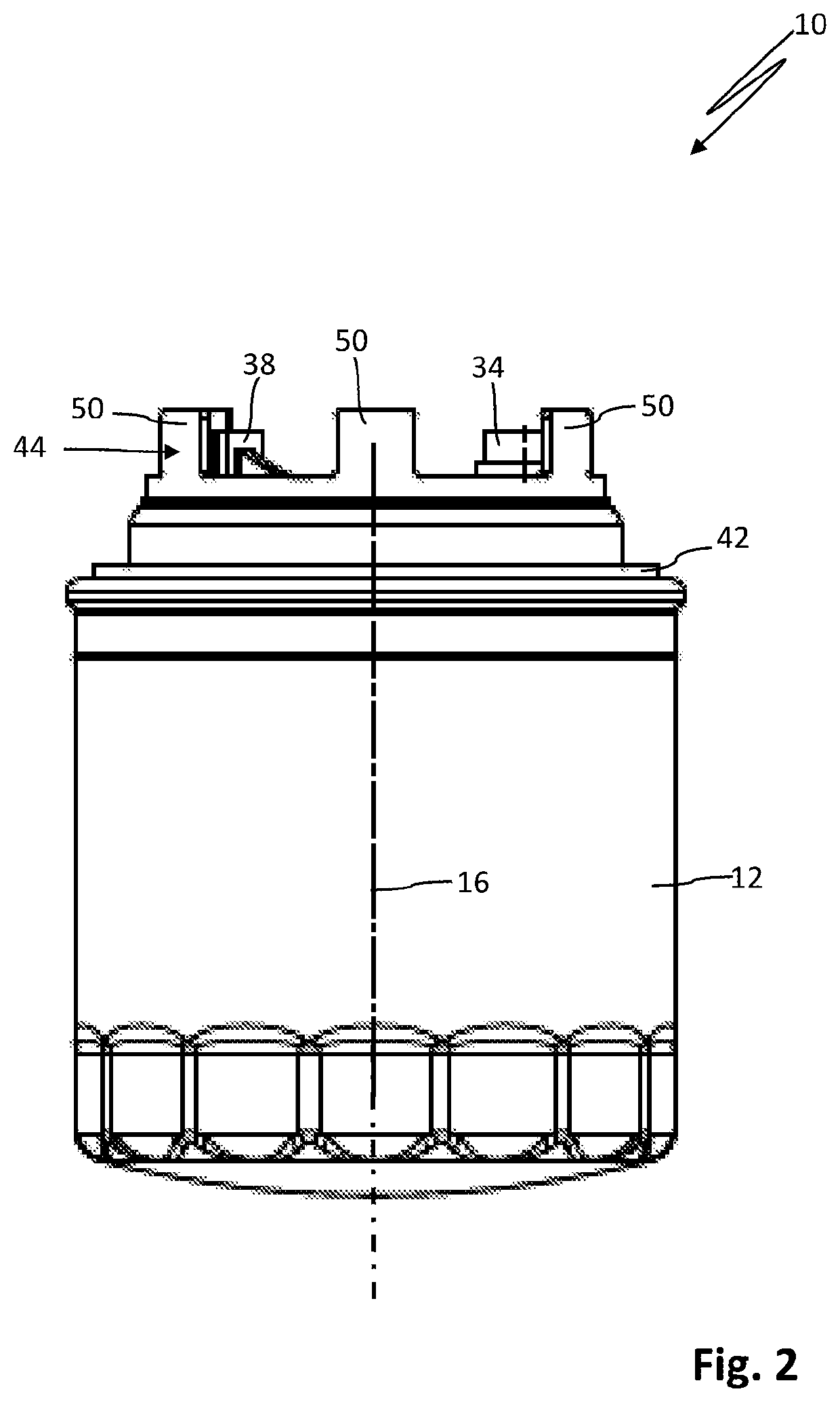
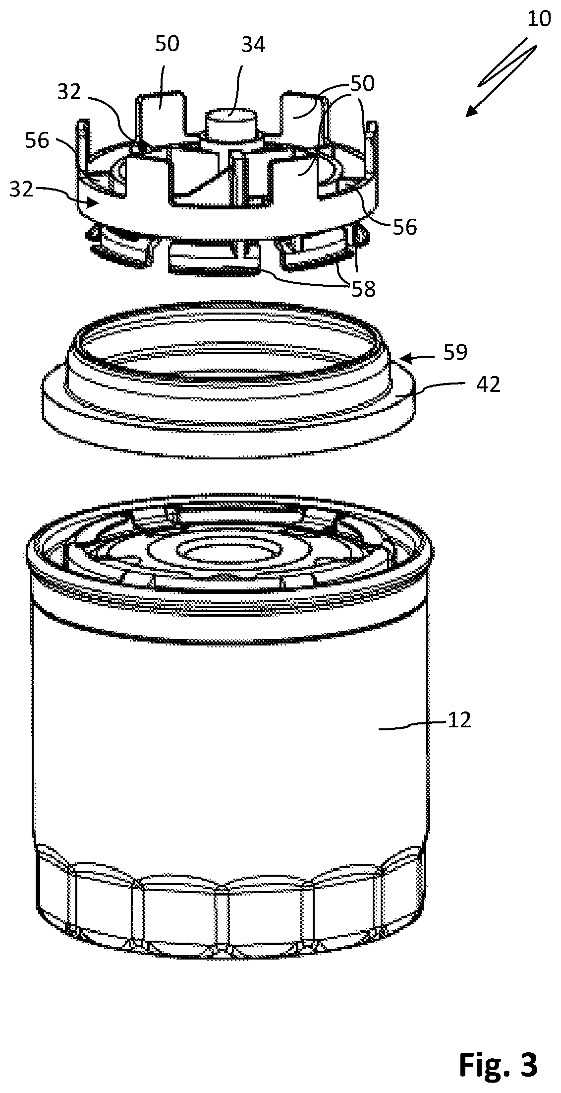
[0032]FIG. 1 shows a filter element 10 for filtering a fluid, in particular lubricant oil for the internal combustion engine of a motor vehicle, which is embodied here in the form of an exchangeable filter cartridge. Such exchangeable filter cartridges are also referred to as spin-on filter cartridges or spin-on filter elements. The filter element 10 comprises thus a filter housing 12 of metal or plastic material and a filter insert 14 with a filter medium arranged captively in the filter housing 12 which is illustrated in FIG. 1 only in a greatly simplified schematic way with dashed line. The longitudinal axis of the filter element 10 is identified by 16.

[0033]The filter element 10 comprises an end face 18 with several inlet openings 20 for the fluid to be filtered and with a single centrally arranged outlet opening 22 for the filtered fluid. The inlet openings 20 are arranged here in an exemplary fashion spaced apart from each other in a ring shape about the longitudinal axis 16. ...


PUM

PropertyMeasurementUnit
Shapeaaaaaaaaaa

Abstract

A filter element for filtering a fluid is connectable to a filter head with a drainage channel. The filter element has a closure element that closes the drainage channel of the filter head when the filter element is connected to the filter head. The closure element is eccentrically arranged relative to a longitudinal axis of the filter element at an end face of the filter element. The closure element extends away from the end face of the filter element in an axial direction of the filter element. A stand is locked at the filter element and extends away from the end face of the filter element in the axial direction to a level of a free end of the closure element or past the free end of the closure element.

Description

CROSS-REFERENCE TO RELATED APPLICATIONS[0001]This application is a continuation application of international application No. PCT / EP2018 / 072104 having an international filing date of 15 Aug. 2018 and designating the United States, the international application claiming a priority date of 15 Aug. 2017 based on prior filed German patent application No. 10 2017 007 653.7 and a priority date of 15 Aug. 2017 based on prior filed German patent application No. 10 2017 007 654.5, the entire contents of the aforesaid international application and the two aforesaid German patent applications being incorporated herein by reference.BACKGROUND OF THE INVENTION[0002]The invention concerns a filter element for the filtration of a fluid, in particular fuel or oil, in particular for the internal combustion engine of a motor vehicle. The filter element comprises a closure element by means of which a drainage channel of a filter head provided for connecting the filter element thereto is closable. The c...

Claims


Application Information

Patent Timeline
IPC IPC(8): B01D35/30B01D35/00
CPCB01D2201/0415B01D35/306B01D2201/291B01D2201/4023B01D35/005B01D35/153B01D35/16B01D27/08B01D27/106B01D2201/4007B01D2201/4046B01D2201/4076B01D2201/347F01M11/03F16N39/06F01M1/10F01M2011/031B01D35/30B01D2201/29B01D2201/304
Inventor LINHART, JOCHENTRAUBLINGER, MARTINERHARDSBERGER, FLORIANSRINIVAS, MAHESHKALLUMGAL, BASIL PAULRAJAGOPAL, NANDAKUMAR
Owner MANN HUMMEL GMBH
Why Eureka
Try Eureka