Shaft Grounding Ring and Dissipation Body for a Shaft Grounding Ring

a technology of shaft grounding ring and dissipation body, which is applied in the direction of rotary current collector, dynamo-electric machines, electrical apparatus, etc., can solve the problems of motors causing frequency-variable interference voltage, destroying motor bearings, disturbing radio reception, etc., and achieves simple and inexpensive manufacture of shaft grounding ring and good dissipation properties

Active Publication Date: 2019-04-11
KACO
View PDF0 Cites 0 Cited by
  • Summary
  • Abstract
  • Description
  • Claims
  • Application Information

AI Technical Summary

Benefits of technology

The shaft grounding ring described in this patent increases the contact surface between the dissipation body and the shaft, which improves the dissipation of charges or voltages. The ring creates different running tracks on the shaft, reducing wear and tear and increasing service life. The flap sections on the ring are distributed onto different tracks, resulting in improved dissipation of induced voltages or electrical charges in the long run. The short T-shaped flap sections are arranged between the long T-shaped flap sections to ensure a good dissipation and large contact surface with a compact configuration.

Problems solved by technology

Electric motors induce frequency-variable interference voltages at the drive shaft.
The interference voltages can inter alia destroy the motor bearings or cause problems in regard to electromagnetic compatibility, for example, disturbing radio reception.
The shaft currents cause at the running surfaces and the bearing balls of the motor bearings small craters caused by melting; this causes the running surfaces of the bearing to become covered with depressions over time and leads to the motor bearing failing in the end.
The employment of the conductive filaments requires a complex and accordingly expensive manufacture of the shaft grounding ring.
In use, there is moreover the risk that the filaments become detached and cause contamination and possibly also damage of the entire system up to the point of total failure of the system.
A problem is also switching the rotational direction of the shaft because the filaments can follow the rotational direction reversal only with difficulty by appropriate adjustment.

Method used


Image

  • Shaft Grounding Ring and Dissipation Body for a Shaft Grounding Ring
  • Shaft Grounding Ring and Dissipation Body for a Shaft Grounding Ring
  • Shaft Grounding Ring and Dissipation Body for a Shaft Grounding Ring

Examples


Embodiment Construction

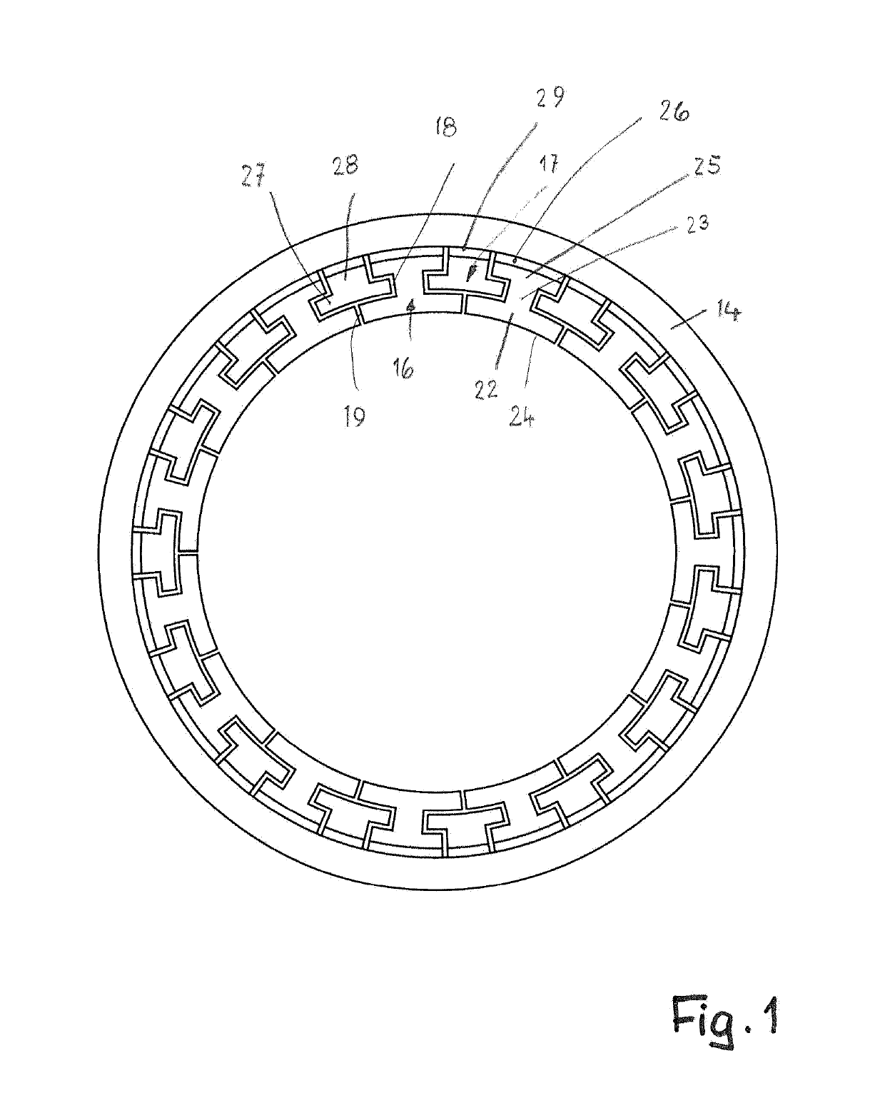
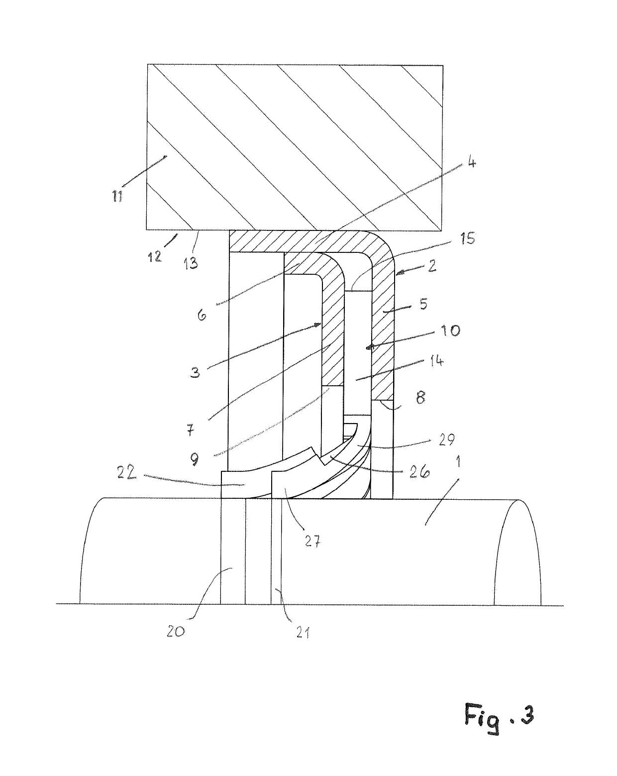
[0040]It is known that converter-operated alternating current motors induce harmful voltages at the motor shaft 1 (FIG. 3). When the voltage surpasses the resistance of the lubricant in a shaft bearing, the voltages will discharge through the shaft bearing that is greatly stressed thereby and will become damaged over longer periods of use. With the shaft grounding rings, the induced harmful voltages in the motor shaft 1 are reliably dissipated so that the voltages no longer are dissipated through the shaft bearing.

[0041]The shaft grounding rings however cannot only be used in motors but, for example, also in transmissions. In general, the shaft grounding rings are employed where induced voltages, currants or electrical charges are to be dissipated away from shafts.

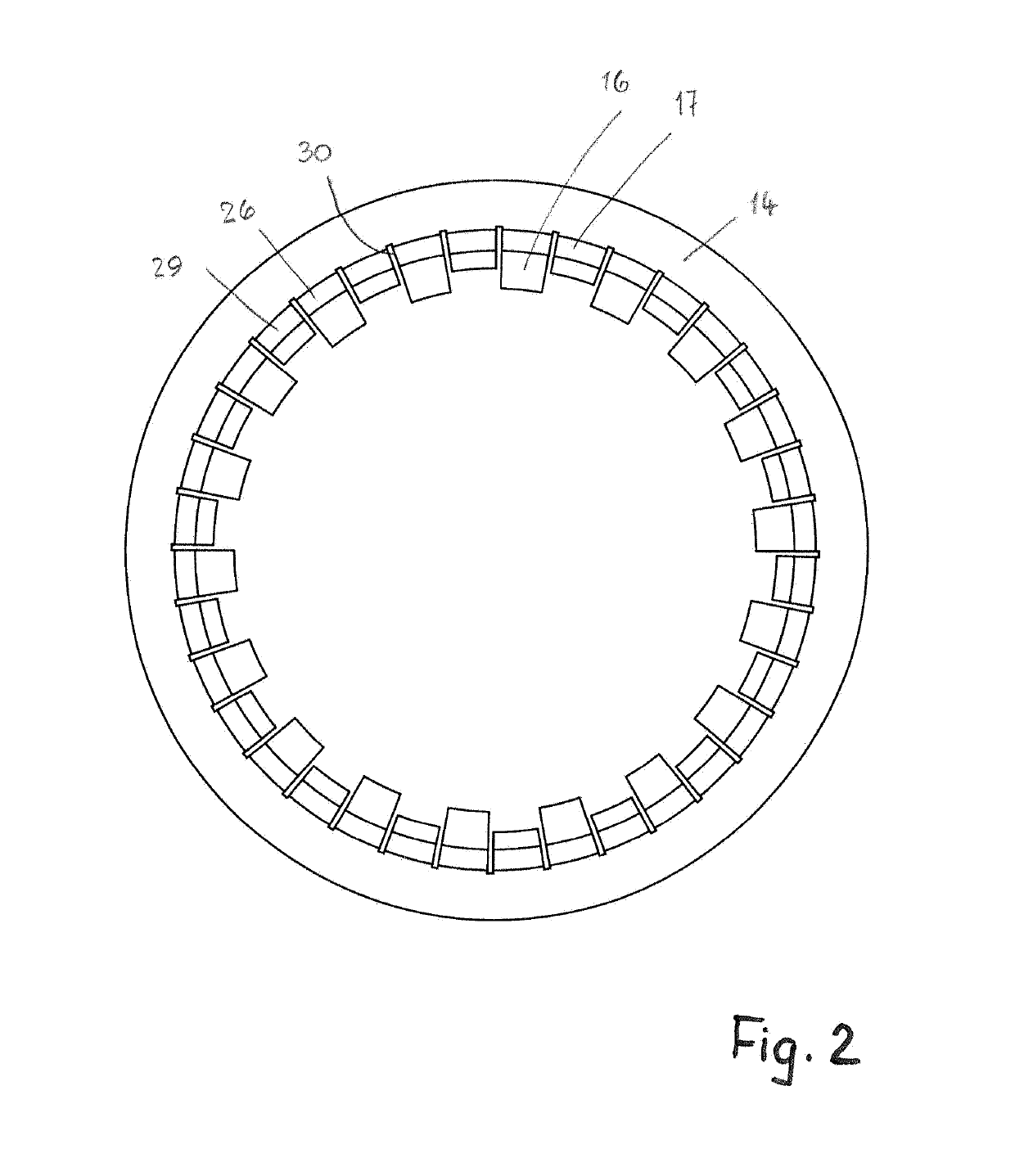
[0042]The shaft grounding ring (FIG. 3) has an outer clamping ring 2 which is comprised of electrically conductive material. The outer clamping ring 2 forms a housing and has an L-shaped cross section in axial section. The...


PUM


Abstract

A shaft grounding ring has an annular housing made of an electrically conductive material and configured to be connected electrically conductively to a first machine element. At least one annular dissipation body electrically conductively connected to the annular housing is provided that is at least partially comprised of an electrically conductive material. The at least one annular dissipation body is configured to be electrically conductively connected to a second machine element. The at least one annular dissipation body has an annular section and further has elastically deformable flap sections connected to the annular section. The flap sections project away from the annular section, wherein the flap sections have different lengths.

Description

BACKGROUND OF THE INVENTION[0001]The invention relates to a shaft grounding ring for dissipating induced voltages or electrical charges away from a first machine element, preferably a shaft, into a second machine element. The shaft grounding ring comprises an annular housing comprised of electrically conductive material that is connected electrically conductively with one of the machine elements and is electrically conductively connected with at least one annular dissipation body which is at least partially comprised of an electrically conductive material and is electrically conductively connected with the other machine element.[0002]The invention further concerns a dissipation body for a shaft grounding ring comprised of an at least partially electrically conductive material and comprising an annular section.[0003]Electric motors induce frequency-variable interference voltages at the drive shaft. The interference voltages can inter alia destroy the motor bearings or cause problems ...

Claims


Application Information

Patent Timeline
Patent Type & Authority Applications(United States)
IPC IPC(8): H02K11/40H02K7/00H02K5/15
CPCH02K11/40H02K7/003H02K5/15H01R4/01H01R39/08
Inventor VAN BEZOOIJEN, LUCAS
Owner KACO
Why Eureka
Try Eureka